NTI KEEMUX Series PS/2 KVM Switch
Unit Address and Loop Back
To allow multiple units to be controlled from a single CPU port, the RS232 control interface is designed to allow "daisy chaining" up to 15 units. By setting the appropriate RS232 dip switches, each unit can be given a unique address
DIP SWITCH |
|
| UNIT ADDRESS | |
8 | 7 | 6 | 5 |
|
OFF | OFF | OFF | OFF | 0 (not valid) |
OFF | OFF | OFF | ON | 1 |
OFF | OFF | ON | OFF | 2 |
OFF | OFF | ON | ON | 3 |
OFF | ON | OFF | OFF | 4 |
OFF | ON | OFF | ON | 5 |
OFF | ON | ON | OFF | 6 |
OFF | ON | ON | ON | 7 |
ON | OFF | OFF | OFF | 8 |
ON | OFF | OFF | ON | 9 |
ON | OFF | ON | OFF | 10 |
ON | OFF | ON | ON | 11 |
ON | ON | OFF | OFF | 12 |
ON | ON | OFF | ON | 13 |
ON | ON | ON | OFF | 14 |
ON | ON | ON | ON | 15 |
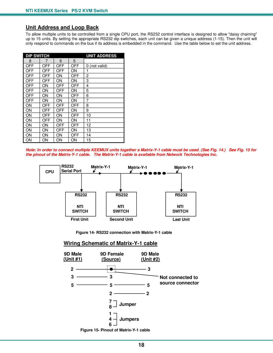
Note: In order to connect multiple KEEMUX units together a
RS232 |
| ||
CPU Serial Port |
|
|
|
RS232 | RS232 | RS232 |
NTI | NTI | NTI |
SWITCH | SWITCH | SWITCH |
First Unit | Second Unit | Last Unit |
Figure 14- RS232 connection with Matrix-Y-1 cable
Wiring Schematic of Matrix-Y-1 cable
9D Male | 9D Female | 9D Male |
|
(Unit #1) | (Source) | (Unit #2) | |
2 |
| 3 |
|
3 | 3 |
| Not connected to |
5 | 5 | 5 | source connector |
| |||
22
7
8 Jumper
1
4Jumpers
Figure 15- Pinout of Matrix-Y-1 cable
18