NTI KEEMUX Series PS/2 KVM Switch
Power Up
1.Turn the KEEMUX power ON first. The mode LEDs on the KEEMUX should flash twice.
2.Turn the monitor power ON.
3.Turn any or all of the CPUs ON.
FYI: Do not press any port buttons on the front panel until the PORT 1 light on the front panel illuminates.
CASCADING
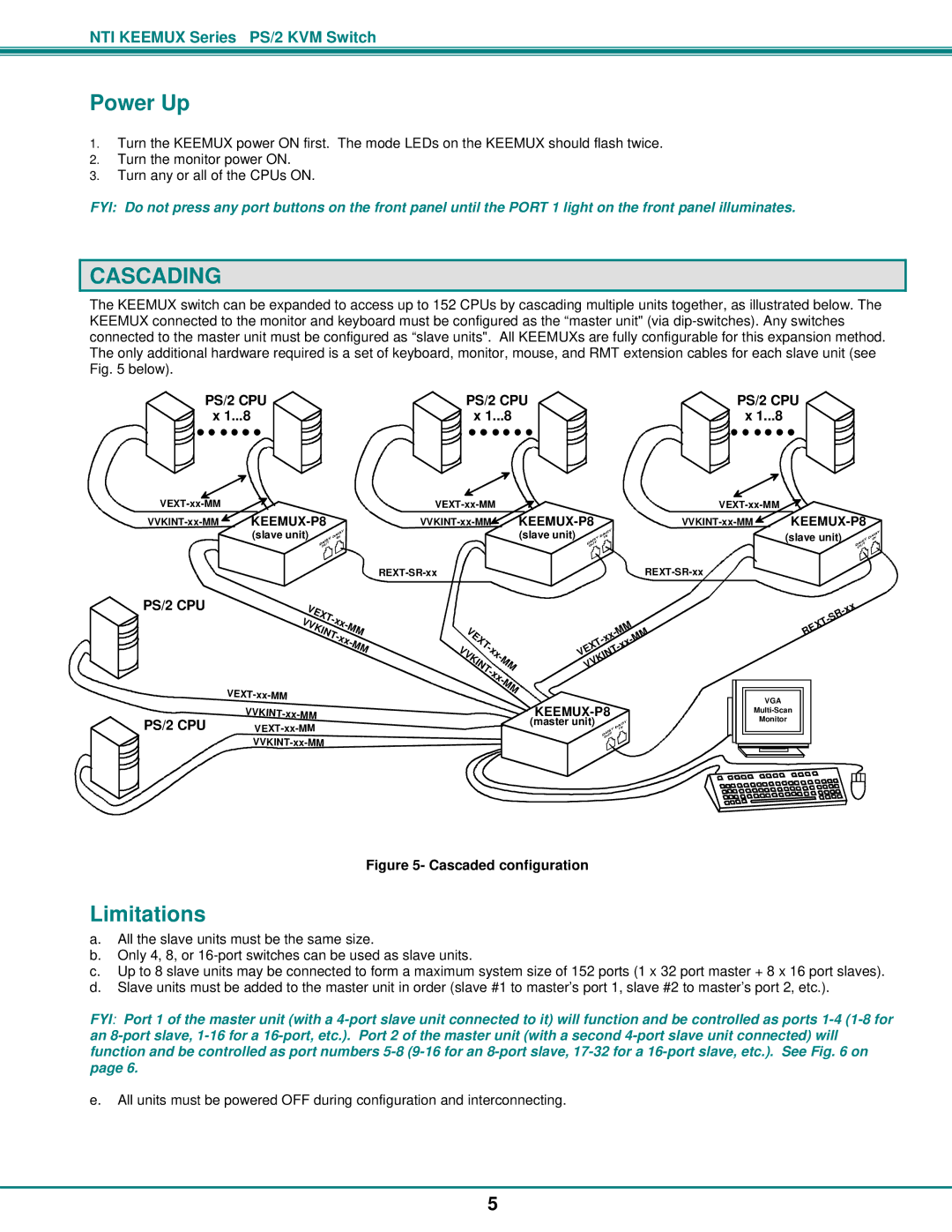
The KEEMUX switch can be expanded to access up to 152 CPUs by cascading multiple units together, as illustrated below. The KEEMUX connected to the monitor and keyboard must be configured as the “master unit" (via
PS/2 CPU | PS/2 CPU | PS/2 CPU |
x 1...8 | x 1...8 | x 1...8 |
|
| |||
| (slave unit) | (slave unit) |
| (slave unit) |
|
|
|
PS/2 CPU | V |
|
|
|
|
|
|
| |
|
| E |
|
|
|
|
| ||
|
|
|
| X |
|
|
|
| |
|
|
|
|
| T- |
|
|
| |
| V | V |
|
|
| x | x |
|
|
|
| KI |
|
| - |
| |||
|
|
|
|
|
| M | M | ||
|
|
|
| N | T- |
| |||
|
|
|
|
|
| xx- |
| ||
|
|
|
|
|
|
|
| M | |
|
|
|
|
|
|
|
|
| M |
|
|
|
|
|
|
|
|
| |
| VVKINT- |
|
|
|
|
|
|
|
|
PS/2 CPU |
|
|
|
|
|
| |||
|
|
|
|
|
| ||||
|
|
|
|
|
| ||||
V |
|
|
| ||
| E |
|
|
| |
|
| X |
|
| |
|
| T |
| ||
V |
|
|
| - |
|
|
|
| x |
| |
V |
|
| x | ||
| K |
|
| - | |
|
|
| M | ||
|
| I |
|
| |
|
| N |
| M | |
|
|
| T |
| |
|
|
|
| - |
|
|
|
|
| x | |
|
|
|
| x | |
|
|
|
|
| - |
|
|
|
|
| M |
|
|
|
|
| M |
|
|
|
|
|
|
| M |
| - |
|
|
| M | ||
|
|
|
| - |
| ||
|
|
|
|
| x |
| |
|
|
|
| x |
|
| |
E |
|
|
| - |
|
|
|
|
| T |
|
|
| ||
V |
| IN |
|
|
|
| |
| K |
|
|
|
|
| |
V |
|
|
|
|
|
| |
V |
|
|
|
|
|
|
|
-
(master unit)
|
|
|
| x |
|
|
|
| |
|
|
| R | |
|
|
|
| |
|
| T |
| |
| X |
|
| |
E |
|
|
| |
R |
|
|
|
|
VGA
Monitor
Figure 5- Cascaded configuration
Limitations
a.All the slave units must be the same size.
b.Only 4, 8, or
c.Up to 8 slave units may be connected to form a maximum system size of 152 ports (1 x 32 port master
d.Slave units must be added to the master unit in order (slave #1 to master’s port 1, slave #2 to master’s
+8 x 16 port slaves). port 2, etc.).
FYI: Port 1 of the master unit (with a
e.All units must be powered OFF during configuration and interconnecting.
5