INTRODUCTION
Top Features | Terminal Panel Features |
56
SE | LE |
CT |
4 | MENU |
SOURCE
4 | 3 | 2 | 1 |
AC IN
LAMP
3![]() STATUS
STATUS ![]() POWER
POWER
ENTER
2
ON/STAND BY
1 7
AUDIO IN | COMPUTER |
5
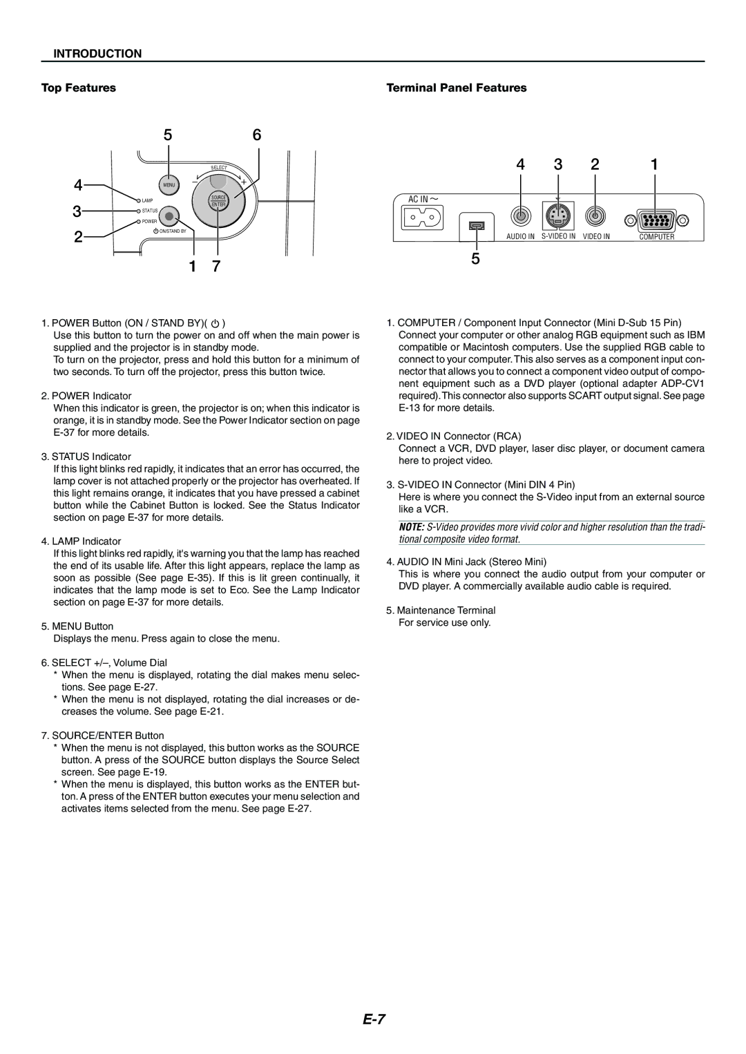
1. POWER Button (ON / STAND BY)( ![]() )
)
Use this button to turn the power on and off when the main power is supplied and the projector is in standby mode.
To turn on the projector, press and hold this button for a minimum of two seconds. To turn off the projector, press this button twice.
2. POWER Indicator
When this indicator is green, the projector is on; when this indicator is orange, it is in standby mode. See the Power Indicator section on page
3. STATUS Indicator
If this light blinks red rapidly, it indicates that an error has occurred, the lamp cover is not attached properly or the projector has overheated. If this light remains orange, it indicates that you have pressed a cabinet button while the Cabinet Button is locked. See the Status Indicator section on page
4.LAMP Indicator
If this light blinks red rapidly, it's warning you that the lamp has reached the end of its usable life. After this light appears, replace the lamp as soon as possible (See page
5.MENU Button
Displays the menu. Press again to close the menu.
6.SELECT
*When the menu is displayed, rotating the dial makes menu selec- tions. See page
*When the menu is not displayed, rotating the dial increases or de- creases the volume. See page
7.SOURCE/ENTER Button
*When the menu is not displayed, this button works as the SOURCE button. A press of the SOURCE button displays the Source Select screen. See page
*When the menu is displayed, this button works as the ENTER but- ton. A press of the ENTER button executes your menu selection and activates items selected from the menu. See page
1.COMPUTER / Component Input Connector (Mini
2.VIDEO IN Connector (RCA)
Connect a VCR, DVD player, laser disc player, or document camera here to project video.
3.
Here is where you connect the
NOTE:
4.AUDIO IN Mini Jack (Stereo Mini)
This is where you connect the audio output from your computer or DVD player. A commercially available audio cable is required.
5.Maintenance Terminal For service use only.