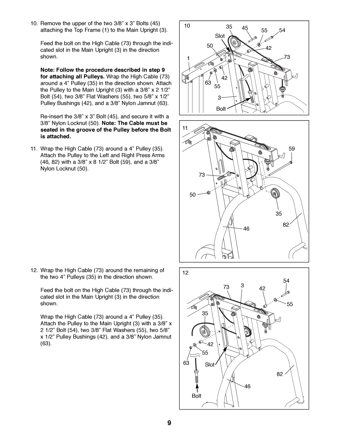
10.Remove the upper of the two 3/8Ó x 3Ó Bolts (45) attaching the Top Frame (1) to the Main Upright (3).
Feed the bolt on the High Cable (73) through the indi- cated slot in the Main Upright (3) in the direction shown.
Note: Follow the procedure described in step 9 for attaching all Pulleys. Wrap the High Cable (73) around a 4Ó Pulley (35) in the direction shown. Attach the Pulley to the Main Upright (3) with a 3/8Ó x 2 1/2Ó Bolt (54), two 3/8Ó Flat Washers (55), two 5/8Ó x 1/2Ó Pulley Bushings (42), and a 3/8Ó Nylon Jamnut (63).
11.Wrap the High Cable (73) around a 4Ó Pulley (35). Attach the Pulley to the Left and Right Press Arms (46, 82) with a 3/8Ó x 8 1/2Ó Bolt (59), and a 3/8Ó Nylon Locknut (50).
12.Wrap the High Cable (73) around the remaining of the two 4Ó Pulleys (35) in the direction shown.
Feed the bolt on the High Cable (73) through the indi- cated slot in the Main Upright (3) in the direction shown.
Wrap the High Cable (73) around a 4Ó Pulley (35). Attach the Pulley to the Main Upright (3) with a 3/8Ó x 2 1/2Ó Bolt (54), two 3/8Ó Flat Washers (55), two 5/8Ó x 1/2Ó Pulley Bushings (42), and a 3/8Ó Nylon Jamnut (63).
10 | 35 | 45 | 55 | 54 |
| Slot |
| ||
|
|
|
| |
50 |
|
| 42 |
|
|
|
|
| |
1 |
|
|
| 73 |
63 | 42 |
|
|
|
55 |
|
|
| |
| 3 |
|
|
|
| Bolt |
|
|
|
11 |
|
|
|
|
|
|
|
| 59 |
73 |
|
|
|
|
50 |
|
|
|
|
|
|
|
| 35 |
|
| 46 |
| 82 |
|
|
|
| |
12 |
|
|
|
|
| 73 | 3 |
| 54 |
| 42 |
| ||
|
|
|
| 55 |
35 |
|
|
|
|
42 |
|
|
|
|
55 |
|
|
|
|
63 ![]() Slot
Slot
82
46
Bolt
9
