Chapter 2 Cabling the VPN Router and turning the power on 49
Quad T1/E1 CSU/DSU WAN interface card LEDs
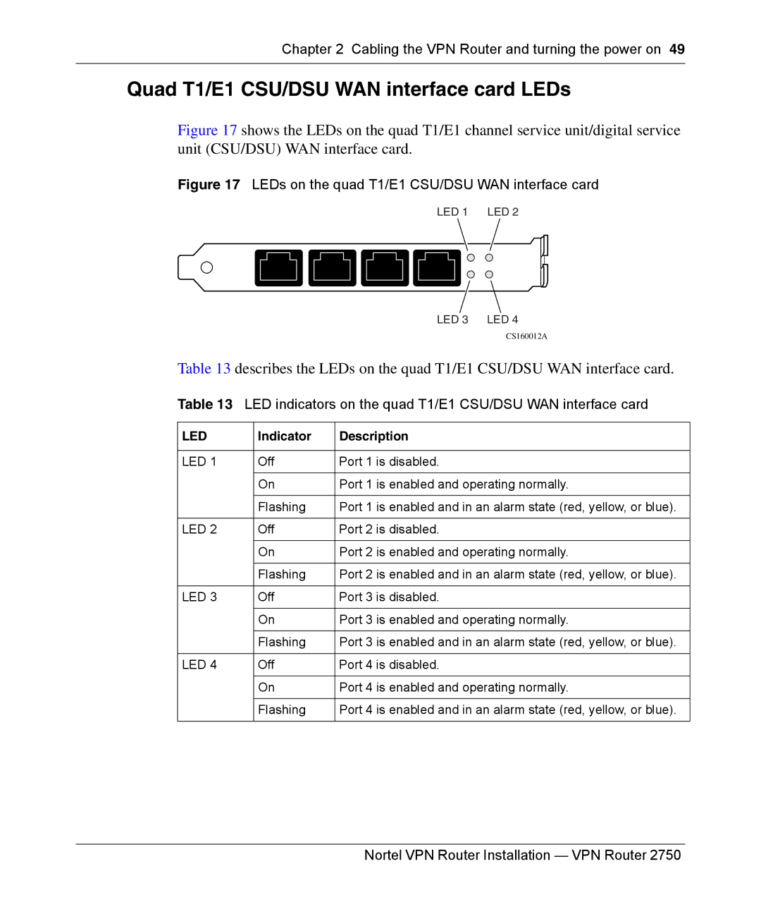
Figure 17 shows the LEDs on the quad T1/E1 channel service unit/digital service unit (CSU/DSU) WAN interface card.
Figure 17 LEDs on the quad T1/E1 CSU/DSU WAN interface card
LED 1 LED 2
LED 3 LED 4
CS160012A
Table 13 describes the LEDs on the quad T1/E1 CSU/DSU WAN interface card.
Table 13 LED indicators on the quad T1/E1 CSU/DSU WAN interface card
LED | Indicator | Description |
|
|
|
LED 1 | Off | Port 1 is disabled. |
|
|
|
| On | Port 1 is enabled and operating normally. |
|
|
|
| Flashing | Port 1 is enabled and in an alarm state (red, yellow, or blue). |
|
|
|
LED 2 | Off | Port 2 is disabled. |
|
|
|
| On | Port 2 is enabled and operating normally. |
|
|
|
| Flashing | Port 2 is enabled and in an alarm state (red, yellow, or blue). |
|
|
|
LED 3 | Off | Port 3 is disabled. |
|
|
|
| On | Port 3 is enabled and operating normally. |
|
|
|
| Flashing | Port 3 is enabled and in an alarm state (red, yellow, or blue). |
|
|
|
LED 4 | Off | Port 4 is disabled. |
|
|
|
| On | Port 4 is enabled and operating normally. |
|
|
|
| Flashing | Port 4 is enabled and in an alarm state (red, yellow, or blue). |
|
|
|
