D. "V" Belts
Warning: Never make adjustments to belts or pulleys while
engine is running!
1.The best tension for a belt drive is the lowest tension at which the belts will not slip under full load.
2.Simply take up the drive until the belts are snug in the grooves. Run the drive for about 15 minutes to "seat" the belts. Then impose the peak load. If the belts slips tighten them until they no longer slip at peak load.
3.Remember too much tension shortens belt and bearing life!
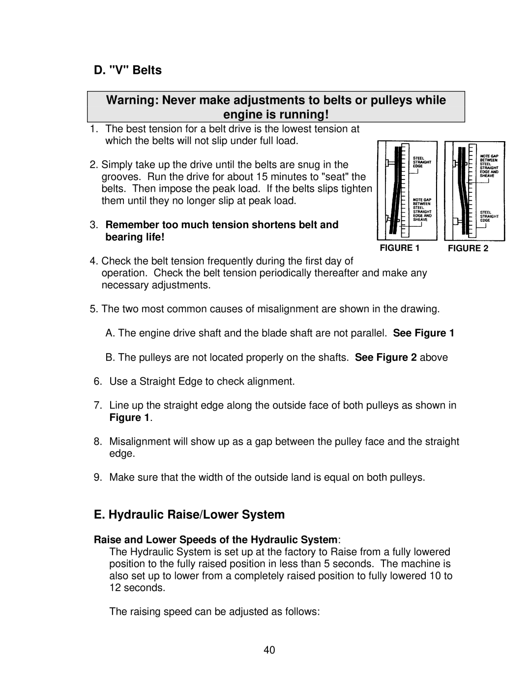
FIGURE 1 | FIGURE 2 |
4.Check the belt tension frequently during the first day of
operation. Check the belt tension periodically thereafter and make any necessary adjustments.
5.The two most common causes of misalignment are shown in the drawing.
A.The engine drive shaft and the blade shaft are not parallel. See Figure 1
B.The pulleys are not located properly on the shafts. See Figure 2 above
6.Use a Straight Edge to check alignment.
7.Line up the straight edge along the outside face of both pulleys as shown in Figure 1.
8.Misalignment will show up as a gap between the pulley face and the straight edge.
9.Make sure that the width of the outside land is equal on both pulleys.
E. Hydraulic Raise/Lower System
Raise and Lower Speeds of the Hydraulic System:
The Hydraulic System is set up at the factory to Raise from a fully lowered position to the fully raised position in less than 5 seconds. The machine is also set up to lower from a completely raised position to fully lowered 10 to 12 seconds.
The raising speed can be adjusted as follows:
40