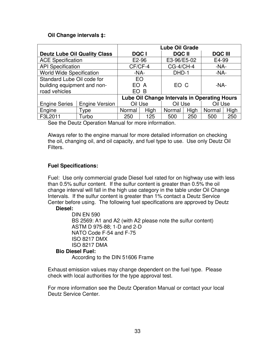
MODELS C3120 C6120 C3126 C6126 C3130 C6130 C6136
Owners Manual
LARGE CONCRETE SAWS
MODEL SERIAL NO PURCHASE FROM ADDRESS CITY STATE ZIP TELEPHONE NO
WARRANTY
Read Owners Manual Before Use
Table of Contents
CONTENTS
III. Maintenance
I. PREPARATION
A. Safety Precautions
DO NOT LIFT THE SAW BY THE HANDLE BARS
Important! The following safety precautions must always be observed
Eye Protection
Dust and Silica Warning
Hearing
Respiratory
A. Safety Precautions
You Are Responsible For Your Safety
I. PREPARATION
B. Assembly
Dimensions/Weight
C. C31xx Concrete Saw Specifications
Characteristics
Engine
Dimensions/Weight
C. C61xx Concrete Saw Specifications
Characteristics
Engine
Read and understand this manual before running or using the machine
A. Installing the Blade
II. OPERATION
Blade Shaft Installation
Changing the Blade Side
B. Aligning the Pointer
For The Best Performance Only Use Norton Diamond Blades
Multiple Mounted Blades
Description
Front Pointer Assembly
Never use a gasoline or an oil and gasoline mixture
C. Controls and Functions
4. Controls/Gauges
Location of Controls and Gauges
Control and Gauge locations and function Chart
Type
Function
Function
Type
5. Starting the Engine
Eye Protection
Straight Drive 31 & 61 HP
D. Water Supply
E. Operating the Saw
Jackshaft Drive 61HP
Hearing
Eye Protection
Respiratory
Head Protection
Jackshaft Drive 61HP
Straight Drive 31 & 61 HP
Transmission While The Machine Is In The Forward Or Reverse Positions
Caution Do Not Engage Or Disengage The
F. Cutting Technique
Depth Gauge
Depth Gauge
Depth Gauge and Depth Lock Locations
Depth Lock
Step Cutting
Additional Guide Lines for Sawing
F. Lead Off Adjustment
Page
A Engine
III. Maintenance
Eye Protection
Hearing
Deutz Engine Components ‡
Locations of Engine Components
Oil Filler Neck and Dipstick Locations ‡
Oil Checking the Oil ‡
Oil Quality Grade
Oil Specifications
Approved Oils
Deutz
Oil Change intervals ‡
Fuel Specifications
Lube Oil Grade
Deutz Lube Oil Quality Class
Winter Fuel Grades
Fault
Engine Service
Measures
Cause
B. Air Filter Assembly
Air Filter C31xx
Dry Cutting Engine Maintenance
Air Filter C61xx
Temperature
C. Bearings
Bearing Location
Shaft Size
engine is running
D. V Belts Warning Never make adjustments to belts or pulleys while
E. Hydraulic Raise/Lower System
3. Remember too much tension shortens belt and bearing life
Adjusting Screw
2. Locate the Check Valve Adjusting Screw as shown below Check Valve
1. Remove the Hydraulic Pump Cover from the console
4. Replace the Hydraulic Pump Cover
Hydraulic Pump Maintenance
Symptom
8. Monarch Hydraulic Pump Symptom /Cause
Motor Start Solenoid Switch
Electrical Switch Open Circuit Motor
d. Volt Meter
c. Continuity Light
e. OHM Meter
10. Hydraulic Fluid a. The Purpose of Oil
1. Fluid must be compatible with Buna N sealing compounds
11. Hydraulic Pump Priming A. New Installations
5. The viscosity index should be as high as possible
A. Viscosity SUS 185 to 205 @ 100OF Viscosity SUS 45 to 50 @ 210OF
12. Hydraulic Pump Electrical Problems
3. A loose or improperly installed suction hose or pick up tube
2. Partially clogged suction filter
4. A bad front pump seal
4. Ground cable size not equivalent or larger than battery cable
C. Cause for Low Voltage 1. Battery capacity too small
6. Burnt contacts on motor solenoid or start switch
1. Remove head assembly from motor
F. Electrical Switches
3. Place a few drops of oil on felt liner in head assembly
1. Use”continuity light to test switch. See Test Equipment Section
4. Check brush set for wear and replace if necessary
G. Motor Start Solenoid Switches
The three post solenoid switch is wired and constructed as follows
H. Shorts, Ground Faults and Open Circuits
A. Relief valve pressure too high 1. Symptoms
12. Diagnosing and Repairing Hydraulic Pump Relief Valves
Amp draw and battery drain excessive when system is dead headed
2. Repair Procedure
13. Diagnosing and Repairing Hydraulic Pump Relief Valves
B. Relief Valve Pressure Too Low 1. Symptoms
The adjusting screw has backed up
Motor RPM is faster than normal Cylinder will not extend
F. Transmission
G. Self-Propelling Operations
Recommended Fluids For Eaton Model 6 Transmissions
7. 20W Straight Viscosity SE, CC, or CD Rated Engine Oil
2. Transmission Engage/Disengage Lever
1. Speed Control Lever
Too Move the Machine
3. Transmission Maintenance
H. Electrical System
Wiring Section “A” Accessory/Switches
Wiring Section “B” Controls/Instruments
BLACK
Wiring Section “C” Wiring Harness Connector
BROWN
YELLOW
BLUE/BLACK
Wiring Section “D” Engine
RED/BLACK
BROWN
A. Ordering Information
IV. PARTS LIST SECTION
Description
Part Number
Straight Drive Non-Jackshaft Models Only
B Blade Guard Conversion Chart
C Service Parts Main Frame Group 31HP and 61HP
Main Frame Group 31HP and 61HP
DESCRIPTION
DESCRIPTION
SHAFT COVER 61 HP
Main Frame Group 31HP and 61HP
Engine Group 61HP
Engine Group 61HP
DESCRIPTION
DESCRIPTION
Engine Group 31HP
Engine Group 31HP
DESCRIPTION
DESCRIPTION
Stub Shaft Group 31HP and 61HP
Sold Individually
Stub Shaft Group 31HP and 61HP
Sold Individually
31HP 12 required
Instrument Panel Group 31HP and 61HP
DESCRIPTION
DESCRIPTION
Transmission and Rear Axle Group 31HP and 61HP
DESCRIPTION
DESCRIPTION
Transmission and Rear Axle Group
Depth Stop and Front Axle Group 31HP and 61HP
DESCRIPTION
DESCRIPTION
Controls and Lever Group
DESCRIPTION
DESCRIPTION
Electro-Hydraulic Group 31HP and 61HP
Electro-Hydraulic Group
DESCRIPTION
DESCRIPTION
Blade Shaft Group Non-Jackshaft 31HP and 61HP
Blade Shaft Group Non-Jackshaft
Blade Guard Group
Blade Guard Group 31HP and 61HP
DESCRIPTION
DESCRIPTION
Water Control System Group
DESCRIPTION
DESCRIPTION
To Water System
Optional Water Pump Group
Exploded View
Assembled View
NOTE Water Pump Kit 237243 items# 1, 2, 3, 4, 5, 6, 8, 9, 10 are includes all
Optional Water Pump Group
2270 West Washington Street Stephenville, TX Phone
Saint-Gobain Abrasives, Inc