Technical Specifications | Appendix A |
A.2.1 SMART-AG Power/Communications Development kit Cable
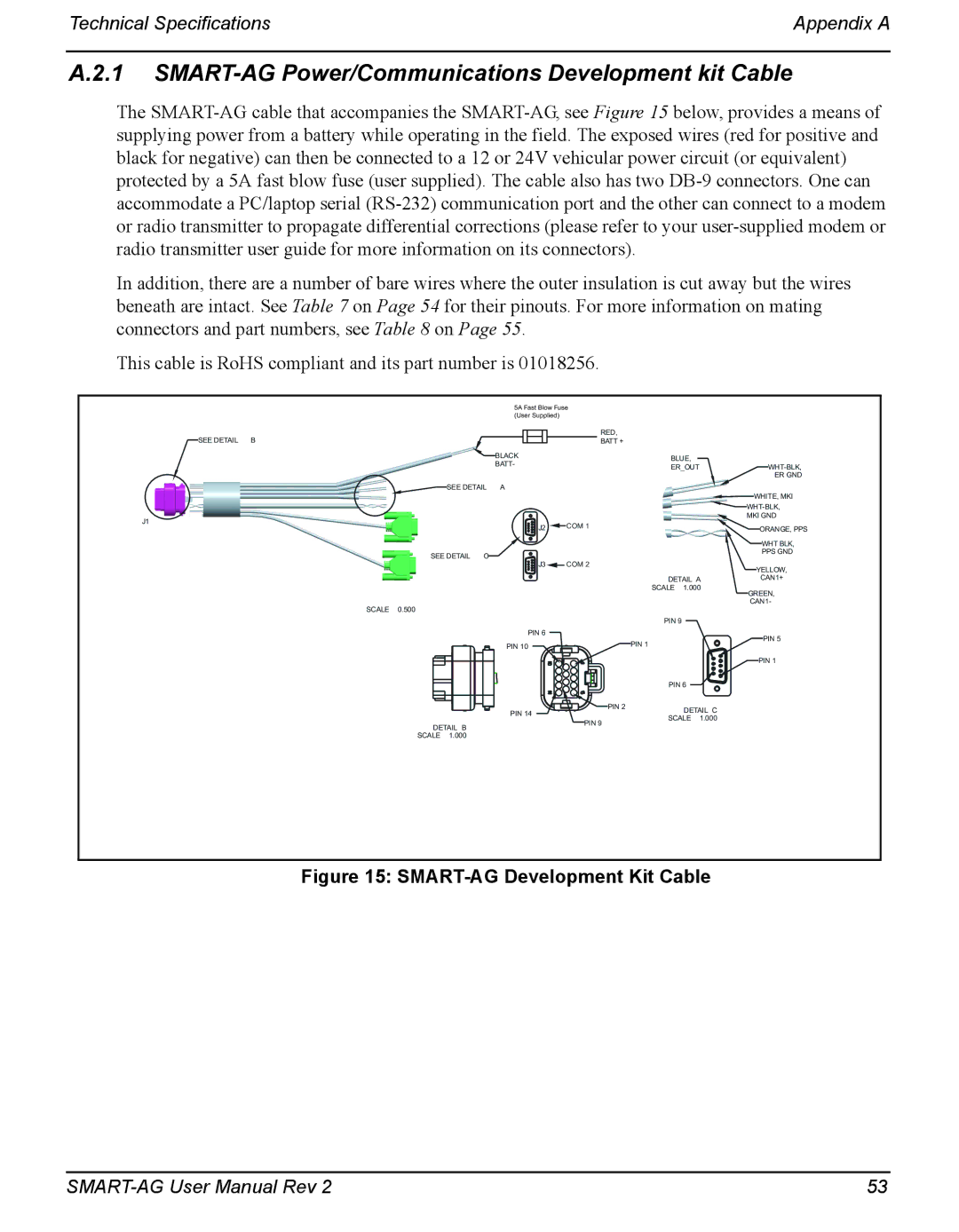
The
In addition, there are a number of bare wires where the outer insulation is cut away but the wires beneath are intact. See Table 7 on Page 54 for their pinouts. For more information on mating connectors and part numbers, see Table 8 on Page 55.
This cable is RoHS compliant and its part number is 01018256.
5A Fast Blow Fuse
(User Supplied)
SEE DETAIL B
![]() BLACK
BLACK
BATT-
![]() SEE DETAIL A
SEE DETAIL A
J1
SEE DETAIL C
STRIP INSULATION FROM
12WIRES AND CRIMP AMP/TYCO TERMINAL #
PER TYCO APPLICATION SPEC
SCALE 0.500
RED,
BATT +
|
|
|
|
| BLUE, |
|
|
|
|
|
|
| |||
|
|
|
|
| ER_OUT |
|
|
|
|
| |||||
|
|
|
|
|
|
| |||||||||
|
|
|
|
|
|
|
|
|
|
|
|
|
|
| ER GND |
|
|
|
|
|
|
|
|
|
|
| WHITE, MKI | ||||
|
|
|
|
|
|
|
|
|
|
| |||||
|
|
|
|
|
|
|
|
|
|
| |||||
| J2 |
|
|
| COM 1 |
| MKI GND | ||||||||
|
|
|
|
|
|
| ORANGE, PPS | ||||||||
|
|
|
|
|
|
|
|
|
|
|
|
|
| WHT BLK, | |
|
|
|
|
|
|
|
|
|
|
|
|
|
| ||
| J3 |
|
|
| COM 2 |
|
|
| PPS GND | ||||||
|
|
|
|
|
|
| |||||||||
|
|
|
|
|
|
|
|
|
|
|
| YELLOW, | |||
|
|
|
|
| DETAIL A |
|
|
| CAN1+ | ||||||
|
|
|
|
| SCALE 1.000 |
| GREEN, | ||||||||
|
|
|
|
|
|
|
|
|
|
| CAN1- | ||||
|
|
|
|
| PIN 9 |
|
|
|
|
|
|
|
|
|
|
|
|
|
|
|
|
|
|
| |||||||
PIN 6 |
|
| PIN 5 |
PIN 10 |
|
| PIN 1 |
|
|
| PIN 1 |
|
|
| PIN 6 |
PIN 14 |
| PIN 2 | DETAIL C |
PIN 9 |
| SCALE 1.000 | |
DETAIL B |
| ||
|
| ||
|
|
| |
SCALE 1.000 |
|
|
|
Figure 15: SMART-AG Development Kit Cable
53 |