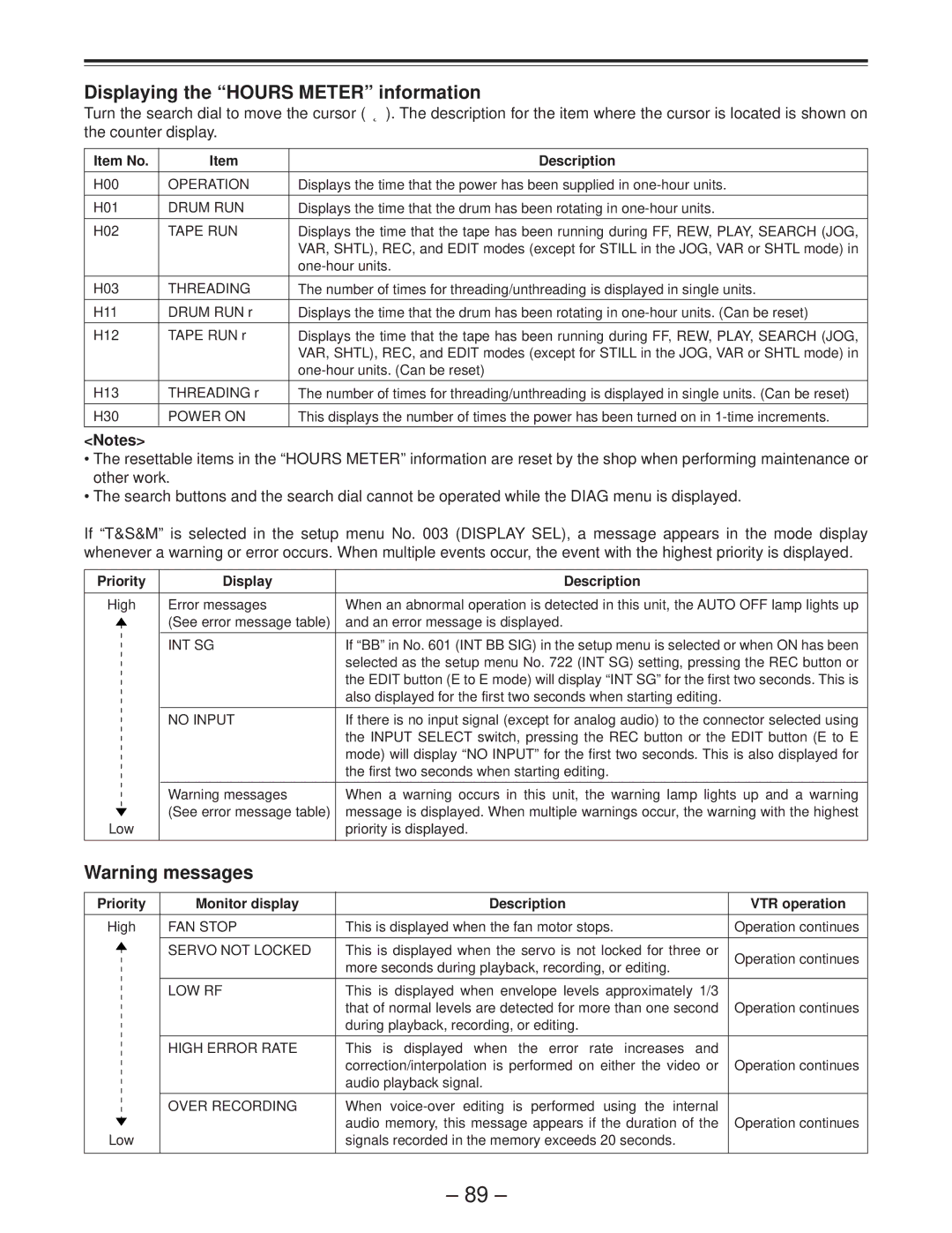
Displaying the “HOURS METER” information
Turn the search dial to move the cursor ( * ). The description for the item where the cursor is located is shown on the counter display.
Item No. | Item | Description |
|
|
|
H00 | OPERATION | Displays the time that the power has been supplied in |
|
|
|
H01 | DRUM RUN | Displays the time that the drum has been rotating in |
|
|
|
H02 | TAPE RUN | Displays the time that the tape has been running during FF, REW, PLAY, SEARCH (JOG, |
|
| VAR, SHTL), REC, and EDIT modes (except for STILL in the JOG, VAR or SHTL mode) in |
|
| |
|
|
|
H03 | THREADING | The number of times for threading/unthreading is displayed in single units. |
|
|
|
H11 | DRUM RUN r | Displays the time that the drum has been rotating in |
|
|
|
H12 | TAPE RUN r | Displays the time that the tape has been running during FF, REW, PLAY, SEARCH (JOG, |
|
| VAR, SHTL), REC, and EDIT modes (except for STILL in the JOG, VAR or SHTL mode) in |
|
| |
|
|
|
H13 | THREADING r | The number of times for threading/unthreading is displayed in single units. (Can be reset) |
|
|
|
H30 | POWER ON | This displays the number of times the power has been turned on in |
<Notes>
•The resettable items in the “HOURS METER” information are reset by the shop when performing maintenance or other work.
•The search buttons and the search dial cannot be operated while the DIAG menu is displayed.
If “T&S&M” is selected in the setup menu No. 003 (DISPLAY SEL), a message appears in the mode display whenever a warning or error occurs. When multiple events occur, the event with the highest priority is displayed.
Priority | Display | Description |
|
|
|
High | Error messages | When an abnormal operation is detected in this unit, the AUTO OFF lamp lights up |
| (See error message table) | and an error message is displayed. |
|
|
|
| INT SG | If “BB” in No. 601 (INT BB SIG) in the setup menu is selected or when ON has been |
|
| selected as the setup menu No. 722 (INT SG) setting, pressing the REC button or |
|
| the EDIT button (E to E mode) will display “INT SG” for the first two seconds. This is |
|
| also displayed for the first two seconds when starting editing. |
|
|
|
| NO INPUT | If there is no input signal (except for analog audio) to the connector selected using |
|
| the INPUT SELECT switch, pressing the REC button or the EDIT button (E to E |
|
| mode) will display “NO INPUT” for the first two seconds. This is also displayed for |
|
| the first two seconds when starting editing. |
|
|
|
| Warning messages | When a warning occurs in this unit, the warning lamp lights up and a warning |
| (See error message table) | message is displayed. When multiple warnings occur, the warning with the highest |
Low |
| priority is displayed. |
|
|
|
Warning messages
Priority | Monitor display | Description | VTR operation |
|
|
|
|
High | FAN STOP | This is displayed when the fan motor stops. | Operation continues |
|
|
|
|
| SERVO NOT LOCKED | This is displayed when the servo is not locked for three or | Operation continues |
|
| more seconds during playback, recording, or editing. | |
|
|
| |
|
|
|
|
| LOW RF | This is displayed when envelope levels approximately 1/3 |
|
|
| that of normal levels are detected for more than one second | Operation continues |
|
| during playback, recording, or editing. |
|
|
|
|
|
| HIGH ERROR RATE | This is displayed when the error rate increases and |
|
|
| correction/interpolation is performed on either the video or | Operation continues |
|
| audio playback signal. |
|
|
|
|
|
| OVER RECORDING | When |
|
|
| audio memory, this message appears if the duration of the | Operation continues |
Low |
| signals recorded in the memory exceeds 20 seconds. |
|
|
|
|
|
– 89 –
