Parts and their functions
Rear panel
5VIDEO OUT (1, 2, Y/G, PB/B, PR/R) connectors By changing the menu item No.615 [V OUT SEL] setting, either analog composite video signals or HD analog component Y (or G) signals are output from the VIDEO OUT1 connector.
By selecting the menu item No.616 [OUT MATRIX] setting, Y/PB/PR or R/G/B signals can be selected as the HD analog component signals.
Video signals with superimposed information embedded can be output from the VIDEO OUT2 connector.
Whether superimposed information is to be embedded in the signals is selected using menu item No.005 [SUPER].
<Notes>
O When HD analog component output or HD SDI output2 signals are output with the 60 Hz or 24 Hz system frequency, the SD SDI2 signals will be output without the sync signals (NO SYNC), and the analog composite signals will be output in the
O A dummy sync signal for preventing the monitor from operating incorrectly is added to the sync signals in the RGB output.
6TC IN connector2
This is used to record an external time code onto the tape.
7TC OUT connector
This is used to output the playback time code during playback.
During recording2, the time code generated by the internal time code generator is output from this connector.
8HD/SD REF VIDEO IN connectors and 75Ω termination switch2
These are the input connectors for the HD/SD reference video signal. For termination, set the switch to ON.
<Notes>
O When inputting an HD reference signal to the connector, input a
O When inputting an SD reference signal to the connector, use composite video signals which satisfy the
9AUDIO IN connectors (CH1, CH2, CH3, CH4)2
These are the input connectors for the analog audio signals.
:AUDIO OUT/MONITOR connector (CH1, CH2, CH3, CH4)
These are the output connectors for the analog audio signals.
The CH3 and CH4 connectors are also used as the audio monitor output connectors (left and right channels). (See page 9)
;AUDIO MONITOR connectors
These are the audio monitor output connectors. The same signals are output as the headphone output signals.
<Note>
The output signal level is fixed.
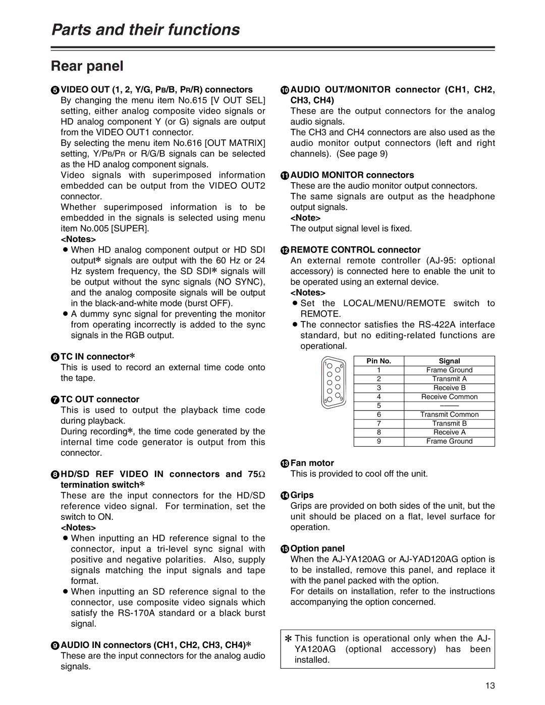
<REMOTE CONTROL connector
An external remote controller
<Notes>
O Set the LOCAL/MENU/REMOTE switch to
REMOTE.
O The connector satisfies the
1 | 6 | Pin No. | Signal |
| 1 | Frame Ground | |
|
| ||
|
| 2 | Transmit A |
|
| 3 | Receive B |
5 | 9 | 4 | Receive Common |
| 5 | ||
|
| ||
|
| 6 | Transmit Common |
|
| 7 | Transmit B |
|
| 8 | Receive A |
|
| 9 | Frame Ground |
=Fan motor
This is provided to cool off the unit.
>Grips
Grips are provided on both sides of the unit, but the unit should be placed on a flat, level surface for operation.
?Option panel
When the
For details on installation, refer to the instructions accompanying the option concerned.
2 This function is operational only when the AJ- YA120AG (optional accessory) has been installed.
13