Side-mounted connection terminals
|
| R/PR | G/Y | B/PB | SYNC/HD | VD |
|
|
|
VIDEO IN |
|
| RGB 1 IN |
|
| RGB 2 IN | LAN | ||
| REMOTE 1 | REMOTE 2 IN | IN | SERIAL | OUT |
|
| ||
| IN | OUT |
|
|
|
|
|
|
|
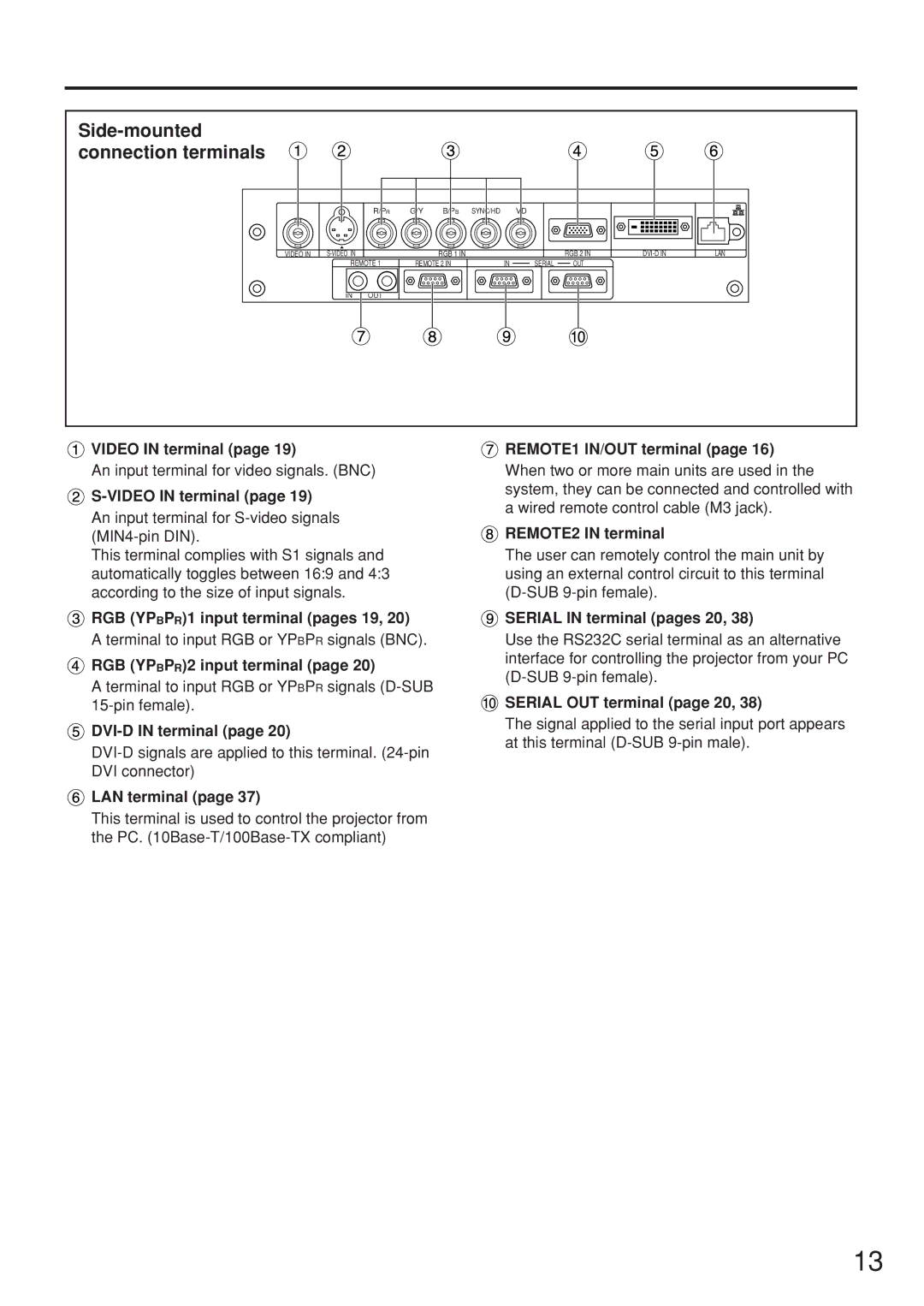
![]() VIDEO IN terminal (page 19)
VIDEO IN terminal (page 19)
An input terminal for video signals. (BNC)
![]()
An input terminal for
This terminal complies with S1 signals and automatically toggles between 16:9 and 4:3 according to the size of input signals.
![]() RGB (YPBPR)1 input terminal (pages 19, 20)
RGB (YPBPR)1 input terminal (pages 19, 20)
A terminal to input RGB or YPBPR signals (BNC).
![]() RGB (YPBPR)2 input terminal (page 20)
RGB (YPBPR)2 input terminal (page 20)
A terminal to input RGB or YPBPR signals
![]()
![]() LAN terminal (page 37)
LAN terminal (page 37)
This terminal is used to control the projector from the PC.
 REMOTE1 lN/OUT terminal (page 16)
When two or more main units are used in the system, they can be connected and controlled with a wired remote control cable (M3 jack).
 REMOTE2 IN terminal
The user can remotely control the main unit by using an external control circuit to this terminal
 SERIAL IN terminal (pages 20, 38)
Use the RS232C serial terminal as an alternative interface for controlling the projector from your PC
![]() SERIAL OUT terminal (page 20, 38)
SERIAL OUT terminal (page 20, 38)
The signal applied to the serial input port appears at this terminal
13