Connection
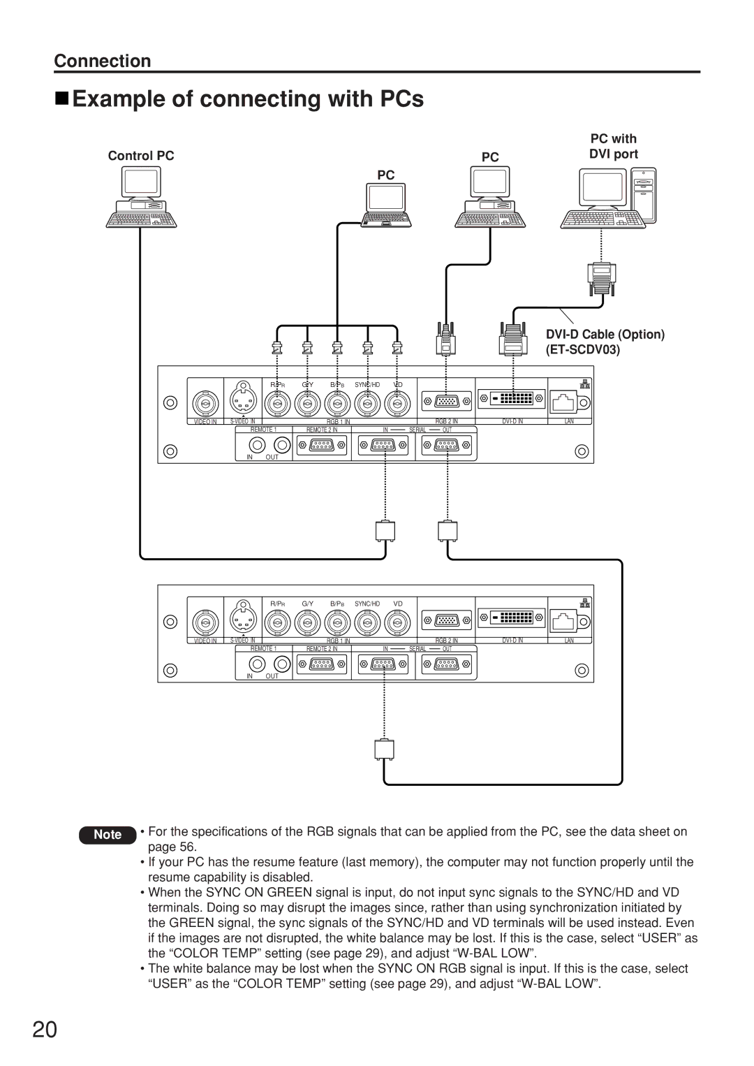
 Example of connecting with PCs
|
| PC with |
Control PC | PC | DVI port |
| PC |
|
DVI-D Cable (Option) (ET-SCDV03)
|
| R/PR | G/Y | B/PB | SYNC/HD | VD |
|
|
|
VIDEO IN |
|
| RGB 1 IN |
|
| RGB 2 IN | LAN | ||
| REMOTE 1 | REMOTE 2 IN | IN | SERIAL | OUT |
|
| ||
| IN | OUT |
|
|
|
|
|
|
|
|
| R/PR | G/Y | B/PB | SYNC/HD | VD |
|
|
|
VIDEO IN |
|
| RGB 1 IN |
|
| RGB 2 IN | LAN | ||
| REMOTE 1 | REMOTE 2 IN | IN | SERIAL | OUT |
|
| ||
| IN | OUT |
|
|
|
|
|
|
|
Note • For the specifications of the RGB signals that can be applied from the PC, see the data sheet on page 56.
•If your PC has the resume feature (last memory), the computer may not function properly until the resume capability is disabled.
•When the SYNC ON GREEN signal is input, do not input sync signals to the SYNC/HD and VD terminals. Doing so may disrupt the images since, rather than using synchronization initiated by the GREEN signal, the sync signals of the SYNC/HD and VD terminals will be used instead. Even if the images are not disrupted, the white balance may be lost. If this is the case, select “USER” as the “COLOR TEMP” setting (see page 29), and adjust
•The white balance may be lost when the SYNC ON RGB signal is input. If this is the case, select “USER” as the “COLOR TEMP” setting (see page 29), and adjust
20
