Connector panel |
|
|
| |
|
|
|
| * |
# | $ | % | & ' | + |
| ||||
|
|
| ( ) |
|
|
|
|
|
|
Wireless card | SD memory card |
| Preparation | |
| Front | LOCK | ' | |
# |
|
| & |
|
$ |
|
|
| |
% |
|
|
|
|
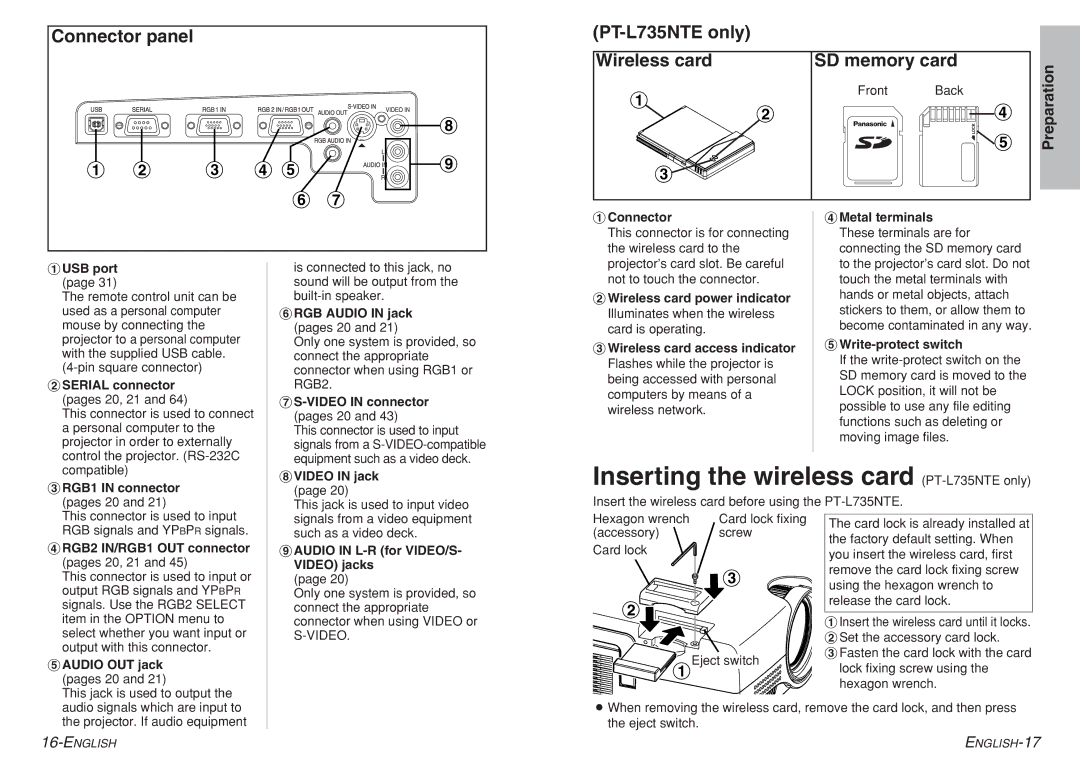
#Connector |
This connector is for connecting |
the wireless card to the |
&Metal terminals |
These terminals are for |
connecting the SD memory card |
#USB port (page 31)
The remote control unit can be used as a personal computer mouse by connecting the projector to a personal computer with the supplied USB cable.
$SERIAL connector |
(pages 20, 21 and 64) |
This connector is used to connect |
a personal computer to the |
projector in order to externally |
control the projector. |
is connected to this jack, no sound will be output from the
(RGB AUDIO IN jack (pages 20 and 21)
Only one system is provided, so connect the appropriate connector when using RGB1 or RGB2.
)S-VIDEO IN connector (pages 20 and 43)
This connector is used to input signals from a
projector’s card slot. Be careful |
not to touch the connector. |
$Wireless card power indicator Illuminates when the wireless card is operating.
%Wireless card access indicator Flashes while the projector is being accessed with personal computers by means of a wireless network.
to the projector’s card slot. Do not |
touch the metal terminals with |
hands or metal objects, attach |
stickers to them, or allow them to |
become contaminated in any way. |
'Write-protect switch
If the
compatible) |
%RGB1 IN connector (pages 20 and 21)
This connector is used to input RGB signals and YPBPR signals.
&RGB2 IN/RGB1 OUT connector (pages 20, 21 and 45)
This connector is used to input or output RGB signals and YPBPR signals. Use the RGB2 SELECT item in the OPTION menu to select whether you want input or output with this connector.
'AUDIO OUT jack (pages 20 and 21)
This jack is used to output the audio signals which are input to the projector. If audio equipment
*VIDEO IN jack (page 20)
This jack is used to input video signals from a video equipment such as a video deck.
+AUDIO IN L-R (for VIDEO/S- VIDEO) jacks
(page 20)
Only one system is provided, so connect the appropriate connector when using VIDEO or
Inserting the wireless card (PT-L735NTE only)
Insert the wireless card before using the
Hexagon wrench | Card lock fixing | The card lock is already installed at | |
(accessory) | screw | ||
the factory default setting. When | |||
Card lock |
| ||
| you insert the wireless card, first | ||
|
| ||
| % | remove the card lock fixing screw | |
| using the hexagon wrench to | ||
|
| ||
$ |
| release the card lock. | |
| #Insert the wireless card until it locks. | ||
|
| ||
|
| $Set the accessory card lock. | |
#Eject switch | %Fasten the card lock with the card | ||
lock fixing screw using the | |||
hexagon wrench.
BWhen removing the wireless card, remove the card lock, and then press the eject switch.