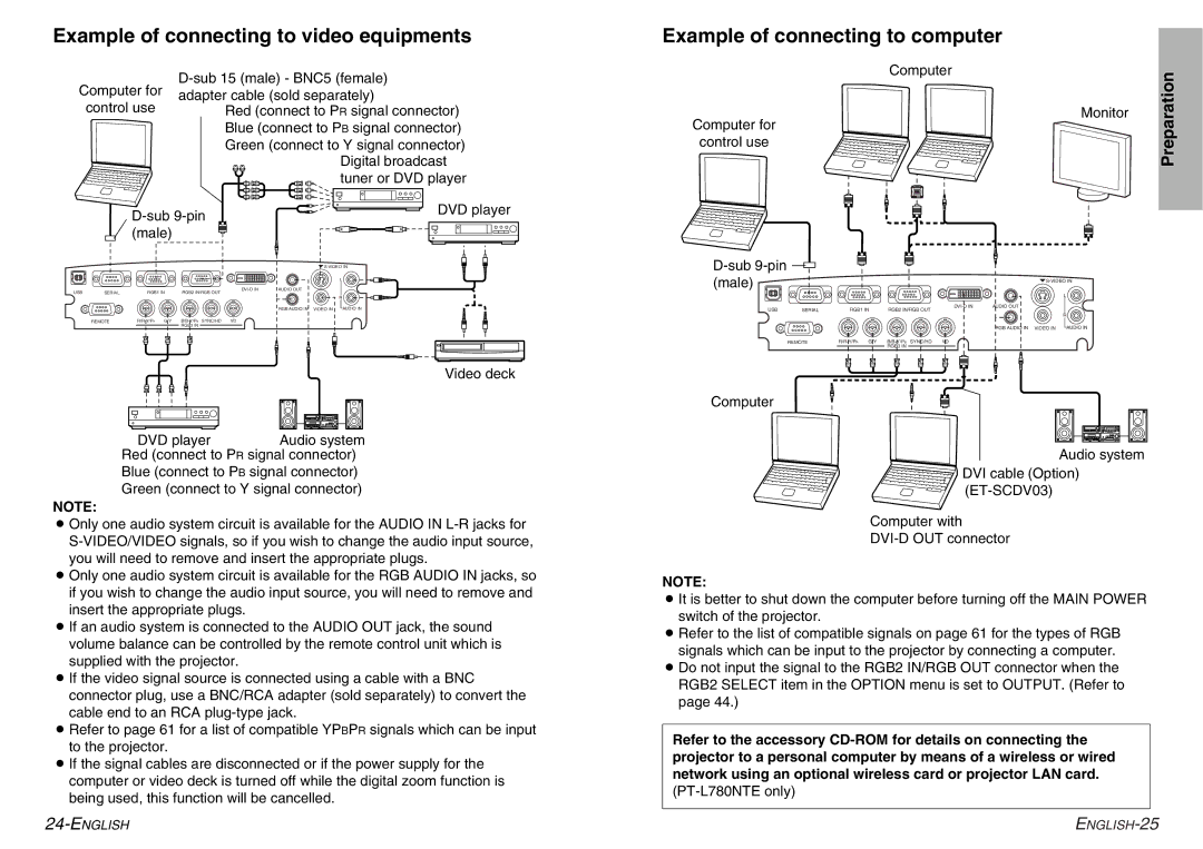
Example of connecting to video equipments
Example of connecting to computer
Computer for
control use
Red (connect to PR signal connector) Blue (connect to PB signal connector) Green (connect to Y signal connector)
Digital broadcast tuner or DVD player
Computer |
| Preparation |
| Monitor | |
|
|
Computer for
control use
|
|
| DVD player | |
|
|
| ||
|
| (male) |
|
|
|
|
|
| |
|
|
|
| L |
USB | SERIAL | RGB1 IN | AUDIO OUT | |
RGB2 IN/RGB OUT | R | |||
|
|
|
| |
|
|
|
| RGB AUDIO IN VIDEO IN AUDIO IN |
| REMOTE |
| ||
|
|
| RGB3 IN |
|
Video deck
DVD playerAudio system
Red (connect to PR signal connector)
Blue (connect to PB signal connector)
Green (connect to Y signal connector)
NOTE:
BOnly one audio system circuit is available for the AUDIO IN
BOnly one audio system circuit is available for the RGB AUDIO IN jacks, so if you wish to change the audio input source, you will need to remove and insert the appropriate plugs.
BIf an audio system is connected to the AUDIO OUT jack, the sound volume balance can be controlled by the remote control unit which is supplied with the projector.
BIf the video signal source is connected using a cable with a BNC connector plug, use a BNC/RCA adapter (sold separately) to convert the cable end to an RCA
BRefer to page 61 for a list of compatible YPBPR signals which can be input to the projector.
BIf the signal cables are disconnected or if the power supply for the computer or video deck is turned off while the digital zoom function is being used, this function will be cancelled.
|
|
|
| |
(male) |
|
|
| |
|
|
|
| L |
USB | SERIAL | RGB1 IN | AUDIO OUT | |
RGB2 IN/RGB OUT | R | |||
|
|
|
| |
|
|
|
| RGB AUDIO IN VIDEO IN AUDIO IN |
| REMOTE |
| ||
|
|
| RGB3 IN |
|
Computer
Audio system
DVI cable (Option)
Computer with
NOTE:
BIt is better to shut down the computer before turning off the MAIN POWER switch of the projector.
BRefer to the list of compatible signals on page 61 for the types of RGB signals which can be input to the projector by connecting a computer.
BDo not input the signal to the RGB2 IN/RGB OUT connector when the RGB2 SELECT item in the OPTION menu is set to OUTPUT. (Refer to page 44.)
Refer to the accessory