Playing a VCR or other peripheral equipment
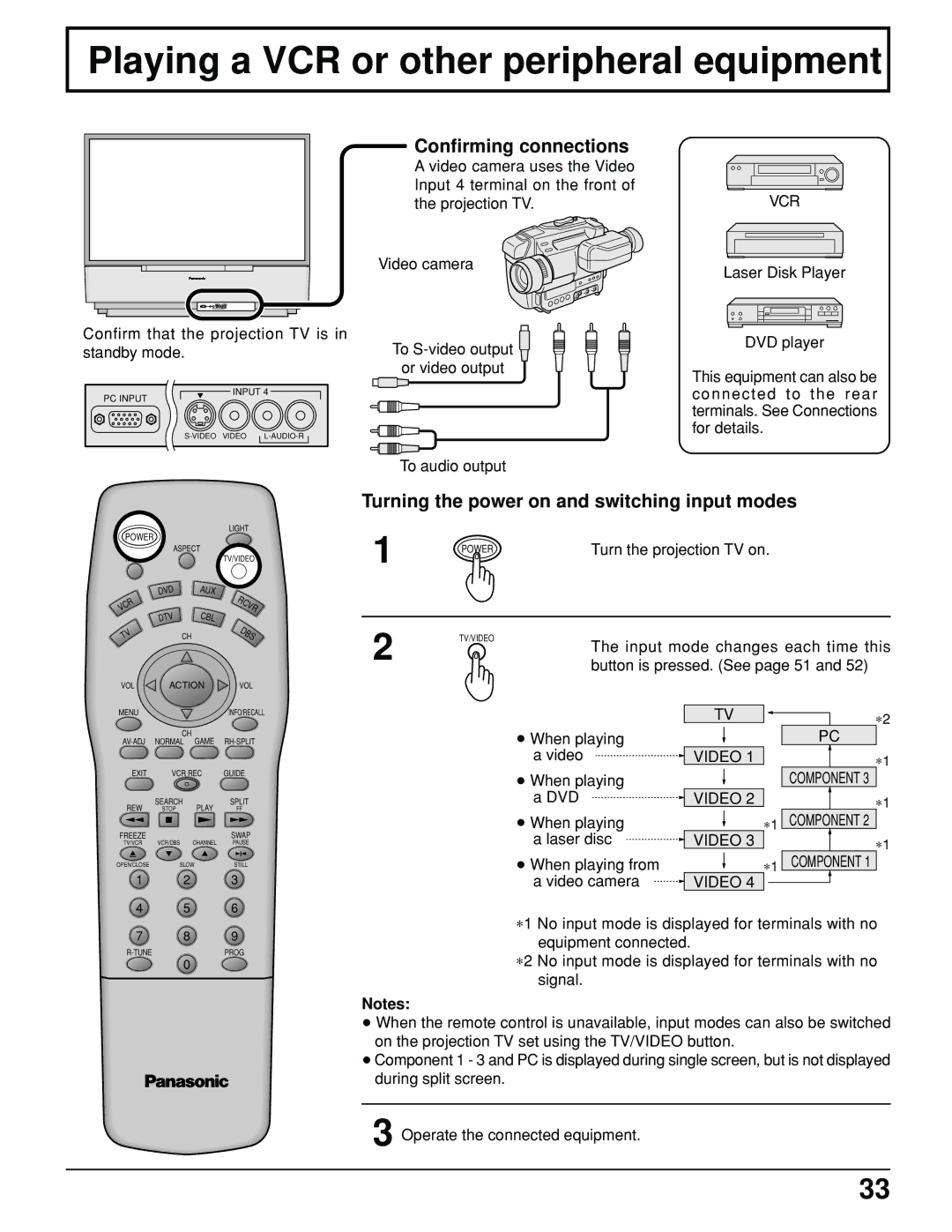
Confirm that the projection TV is in standby mode.
INPUT 4
PC INPUT
Confirming connections
A video camera uses the Video Input 4 terminal on the front of the projection TV.
Video camera
To ![]() or video output
or video output
To audio output
VCR
Laser Disk Player
DVD player
This equipment can also be connected to the rear terminals. See Connections for details.
LIGHT
POWER
ASPECT
MUTETV/VIDEO
| DVD | AUX | RCVR |
VCR |
| CBL | |
| DTV |
| |
TV |
| CH | DBS |
VOL | ACTION | VOL | |
Turning the power on and switching input modes
1 | POWER | Turn the projection TV on. |
|
2 | TV/VIDEO | The input mode changes each time this |
|
| |
|
| button is pressed. (See page 51 and 52) |
MENU |
|
| INFO/RECALL |
| CH |
|
|
EXIT | VCR REC | GUIDE | |
REW | SEARCH | PLAY | SPLIT |
STOP | FF | ||
FREEZE |
|
| SWAP |
TV/VCR | VCR/DBS | CHANNEL | PAUSE |
OPEN/CLOSE | SLOW | STILL | |
1 2 3
4 5 6
•When playing a video
•When playing a DVD
•When playing a laser disc
•When playing from a video camera
TV
VIDEO 1
VIDEO 2
∗ 1
VIDEO 3
∗ 1
VIDEO 4
∗ 2
PC
∗ 1
COMPONENT 3
∗ 1
COMPONENT 2
∗ 1
COMPONENT 1
7 8 9
0
∗1 No input mode is displayed for terminals with no equipment connected.
∗2 No input mode is displayed for terminals with no signal.
Notes:
•When the remote control is unavailable, input modes can also be switched on the projection TV set using the TV/VIDEO button.
•Component 1 - 3 and PC is displayed during single screen, but is not displayed during split screen.
3 Operate the connected equipment.
33
