8PS • Data
Address Assignment
|
|
|
|
| UNIT Switch Position |
|
|
|
| ||
| 0 | 1 | 2 | 3 | 4 | 5 | 6 | 7 | 8 | 9 | |
Unit address | Set the |
|
|
|
|
|
|
|
| Do not | |
number in | 1 |
|
|
|
|
|
|
| |||
2 | 3 | 4 | 5 | 6 | 7 | 8 | use, | ||||
given to | Setup | ||||||||||
|
|
|
|
|
|
|
| reserved | |||
| menu |
|
|
|
|
|
|
|
| ||
|
|
|
|
|
|
|
|
|
| ||
8Camera Communication Protocol
As shown in the table, the UNIT switch determines the camera unit numbers.
Address Assignment
|
|
|
|
|
| UNIT Switch Position |
|
|
|
| ||
|
|
|
|
|
|
|
|
|
|
|
|
|
|
| 0 | 1 | 2 | 3 |
| 4 | 5 | 6 | 7 | 8 | 9 |
|
|
|
|
|
|
|
|
|
|
|
|
|
| 1 | Set the | 1 | 5 | 9 |
| 13 | 17 | 21 | 25 | 29 |
|
|
|
|
|
|
|
|
|
|
|
| Do not | |
Connector | 2 | 2 | 6 | 10 |
| 14 | 18 | 22 | 26 | 30 | ||
number in |
| |||||||||||
CAMERA IN/OUT |
| Setup |
|
|
|
|
|
|
|
|
| use, |
3 | 3 | 7 | 11 |
| 15 | 19 | 23 | 27 | 31 | |||
| reserved | |||||||||||
|
| menu |
|
|
|
|
|
|
|
|
|
|
| 4 | 4 | 8 | 12 |
| 16 | 20 | 24 | 28 | 32 |
| |
|
|
|
| |||||||||
|
|
|
|
|
|
|
|
|
|
|
|
|
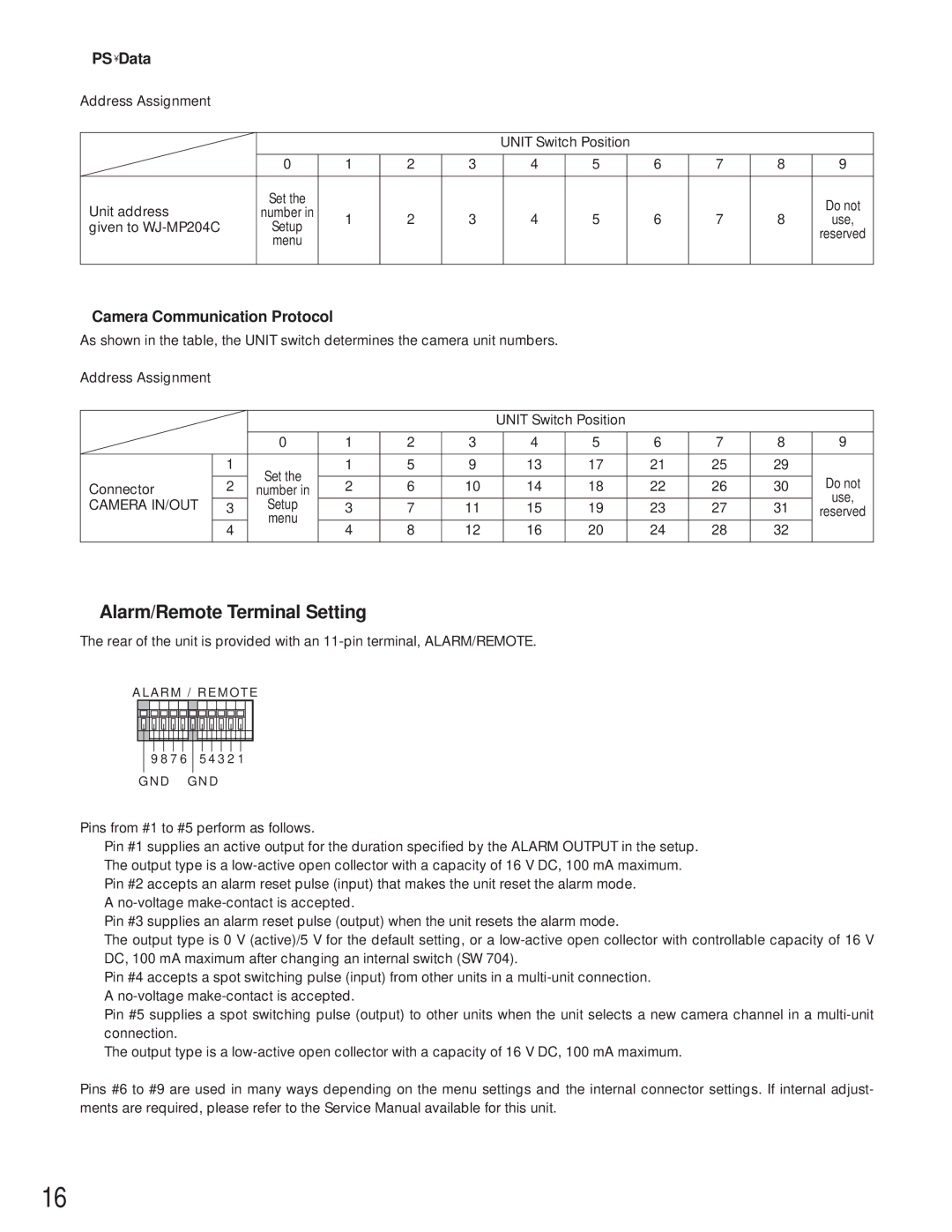
●Alarm/Remote Terminal Setting
The rear of the unit is provided with an
ALARM / REMOTE
|
|
|
|
|
|
|
|
|
|
|
|
|
|
|
|
|
|
|
|
|
|
|
|
|
|
|
|
|
|
|
|
|
|
|
|
|
|
|
|
|
|
|
|
|
|
|
|
|
|
|
|
|
|
|
|
|
|
|
|
|
|
|
|
|
|
|
|
|
|
|
|
|
|
|
|
|
|
| 9 8 7 6 | 5 4 3 2 1 |
| |||||||||
|
|
|
|
|
|
|
|
|
|
|
|
|
GND | GND | |||||||||||
Pins from #1 to #5 perform as follows.
Pin #1 supplies an active output for the duration specified by the ALARM OUTPUT in the setup. The output type is a
A
Pin #3 supplies an alarm reset pulse (output) when the unit resets the alarm mode.
The output type is 0 V (active)/5 V for the default setting, or a
Pin #4 accepts a spot switching pulse (input) from other units in a
Pin #5 supplies a spot switching pulse (output) to other units when the unit selects a new camera channel in a
The output type is a
Pins #6 to #9 are used in many ways depending on the menu settings and the internal connector settings. If internal adjust- ments are required, please refer to the Service Manual available for this unit.
16