2.Move the cursor to COMP. Select a parameter with the
The longer a coaxial cable is extended, the more the video signals attenuate. This setting is to compensate signal attenuation in 3 degrees. Select the best para- meter that optimizes the displayed image on the moni- tor while observing it.
S:Short distance of less than 1 300 ft (400 m)
M:Medium distance between 1 300 ft (400 m) and 2 300 ft (700 m)
L:Long distance of less than 3 000 ft (900 m)
Note: Distance is based on the assumption that RG- 59U, BELDEN 9259 or equivalent cable is used.
3.Move the cursor to VD2. Select a parameter with the
The VD2 sync signal is multiplexed onto the coaxial cable and sent to the camera for synchronization. Refer to the table on page 23 for detailed
ON: VD2 synchronizes with the input to the VS/VD con- nector when supplied, or with the internal sync when VS/VD has no input.
THRU: VD2 is supplied when a camera out connector accepts external VD2 from the connected device. No VD2 is supplied when no camera out connector accepts external VD2.
OFF: No VD2 is supplied to the camera.
4.Move the cursor to DATA. Select ON or OFF with the
Data communication with the selected camera channel is enabled or disabled.
ON: Enabled.
OFF: Disabled.
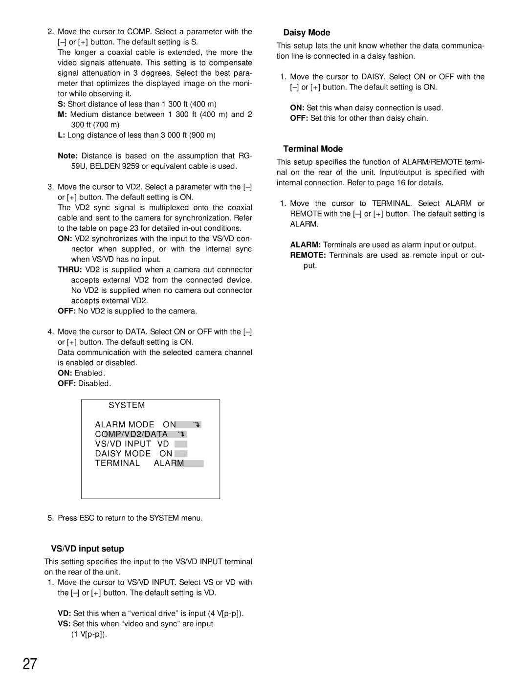
SYSTEM |
|
|
|
| ||
ALARM MODE |
|
| ||||
ON | ||||||
|
|
|
|
|
|
|
COMP/VD2/DATA |
|
|
|
| ||
VS/VD INPUT |
|
|
|
|
| |
| VD | |||||
DAISY MODE |
|
|
|
| ||
| ON | |||||
TERMINAL |
|
|
| |||
| ALARM | |||||
5. Press ESC to return to the SYSTEM menu.
8VS/VD input setup
This setting specifies the input to the VS/VD INPUT terminal on the rear of the unit.
1.Move the cursor to VS/VD INPUT. Select VS or VD with the
VD: Set this when a “vertical drive” is input (4
VS: Set this when “video and sync” are input (1
8Daisy Mode
This setup lets the unit know whether the data communica- tion line is connected in a daisy fashion.
1.Move the cursor to DAISY. Select ON or OFF with the
ON: Set this when daisy connection is used.
OFF: Set this for other than daisy chain.
8Terminal Mode
This setup specifies the function of ALARM/REMOTE termi- nal on the rear of the unit. Input/output is specified with internal connection. Refer to page 16 for details.
1.Move the cursor to TERMINAL. Select ALARM or REMOTE with the
ALARM.
ALARM: Terminals are used as alarm input or output.
REMOTE: Terminals are used as remote input or out- put.
27