IPLink Series High Speed Routers
Mailsupport@patton.com
Summary Table of Contents
Contents
Models 2603, 2621, and 2635 Getting Started Guide
Remote Site Configuration Central site configuration
EMC
Ethernet Cable 123 Adapter
Models 2603, 2621, and 2635 Getting Started Guide
List of Figures
Models 2603, 2621, and 2635 Getting Started Guide
List of Tables
Audience
About this guide
Structure
Safety when working with electricity
Precautions
Impaired functioning
General observations
Factory default parameters
General conventions
Typographical conventions used in this document
General Information
Chapter contents
General attributes
IPLink Series High Speed Routers overview
WAN Interfaces
Ethernet
Protocol support
PPP Support
Security
Logging or Smtp on events POST, Post errors, PPP/DHCP, IP
Front Panel Status LEDs and Console Port
Console port
Rear panel connectors and switches
On the rear panel from left to right are the following
Ethernet port outlined in green
Power connector
General Information
Product Overview
Introduction
Sync Serial Application
Applications Overview
Initial Configuration
Interface cable installation
Hardware installation
What you will need
RJ-48C pinout diagram
Initial Configuration
Ethernet connector Interface connector RJ-45 DB-15
Case being opened with a screwdriver
Ethernet connector Interface connector RJ-45 DB-25
DCE
Installing the AC power cord
Initial Configuration
Do the following
Installing the Ethernet cable
PC Configuration
IP address modification
IP address has now been successfully changed
Web Operation and Configuration
Model 2603 home
Model 2635 home
Ethernet LAN Port
Ethernet Port
LAN Connections
Basic Ethernet port attributes
Configurable Ethernet parameters
Serial Port Configuration
Serial Interface
WAN Serial Port Configuration
Variables
T1/E1 Interface Configuration
Web Interface Configuration
Web Configuration , enter username See figure
Configuring the IPLink Series 2603 for T1 Operation
Configuring the IPLink Series 2603 for E1 Operation
Line Options Fractional T1
Serial Port Configuration
PPP Bridged
WAN Services
WAN Services
PPP Configuration
WAN Service Configuration
PPP Bridged
Leave User name and Password blank. Click on Create
Remote site configuration
PPP Routed
PPP Routed Configuration menu
Click on Create
Edit IP address of WAN port
Click the Update button
PPP link status
LMI Management Frame Relay links
Username blank Password blank Click on the Create button
LMI Configuration
Web Configuration Methods
Dlci Number Use
Frame Relay Configuration
Frame Relay bridged creation
Frame Relay bridged
Central site configuration
Relay
Frame Relay Routed
Description FR routed
Frame Relay Channel Routed configuration
IP route for Frame Relay routed application
Cost Interface frame-0
WAN Services
Security
Configuring the router
Click on Create a new service
Click on the Create a new Ip route... hyperlink
Valid gateway route
Configuring the security interfaces
Security configuration home
Click on the hyperlink New Policy... See figure
Configuring Security Policies
Firewall Portfilters
Enabling the Firewall
Deleting a security Policy
You can now ping between the two networks
Security Triggers
Configuring TCP port filter for FTP
Adding trigger for FTP data transfer
Attack Name Protocol Attacking Host Blacklisted?
Intrusion Detection System IDS
Security
Enabling NAT
Introduction to NAT
Global address pool and reserved map
Click on Add Global Address Pool button
Dhcp and DNS Configuration
Services and features normally associated with each other
NAT
Dhcp Server
Dhcp Server web
Dhcp server configuration web
Parameters for the Dhcp Server subnet
Next section see figure 58. has three parameters
IP Addresses to be available on this subnet
DNS server option information
Example based on default range of IP address pool
Configuration of the Dhcp Relay
Default gateway option information
Additional option information
Dhcp Relay
Dhcp Relay webpage
Configuring the DNS Relay
DNS Relay
DNS Relay configuration webpage
IP Services
CLI Configuration
IP Services
Next command disables the WEB server
WEB Server
Associated Ports for the different System IP Services
System Configuration
Authentication web page showing default superuser
Authentication
Access the configuration and status of the alarms
Alarm
Alarm & Alarm Error Log configuration
Remote Access
Backup/Restore
Update
Save
Restart
Website Settings
Snmp Daemon
Error Log
Snmp Daemon configuration
System Tools
Sntp Client Configuration
Configuring the Sntp Client
Sntp Client Mode Configuration Parameters
Sntp Client General Configuration Parameters
System Clock Setting
Configuration of the internal system calendar clock
System Status
Port Connection Status
System Status
Hardware Status
LAN Status
MAC address the MAC address of the Ethernet port
WAN Status
Status LEDs
Contacting Patton for assistance
Contact information
Warranty coverage
Patton support headquarters in the USA
RMA numbers
Out-of-warranty service
Returns for credit
Return for credit policy
EMC
Appendix a Compliance information
FCC Part 68 Acta Statement Model 2603 only
Compliance
Radio and TV Interference FCC Part
CE Declaration of Conformity
Industry Canada Notice 2603 Model only
Appendix B Specifications
T1/E1 Interface
General Characteristics
Ethernet
Sync Serial Interface
PPP Support
Protocol Support
Management
VDC power supply
Dimensions
Power and Power Supply Specifications
AC universal power supply
Appendix C Cable Recommendations
Adapter
Ethernet Cable
Appendix D IPLink Physical Connectors
RJ-45 shielded 10/100 Ethernet port
Assuming the MDI-X switch is in the out position
RJ-45 non-shielded RS-232 console port EIA-561
Serial port
35 M/34 and DB-25 Connector
Pin No Circuit Signal Name Direction
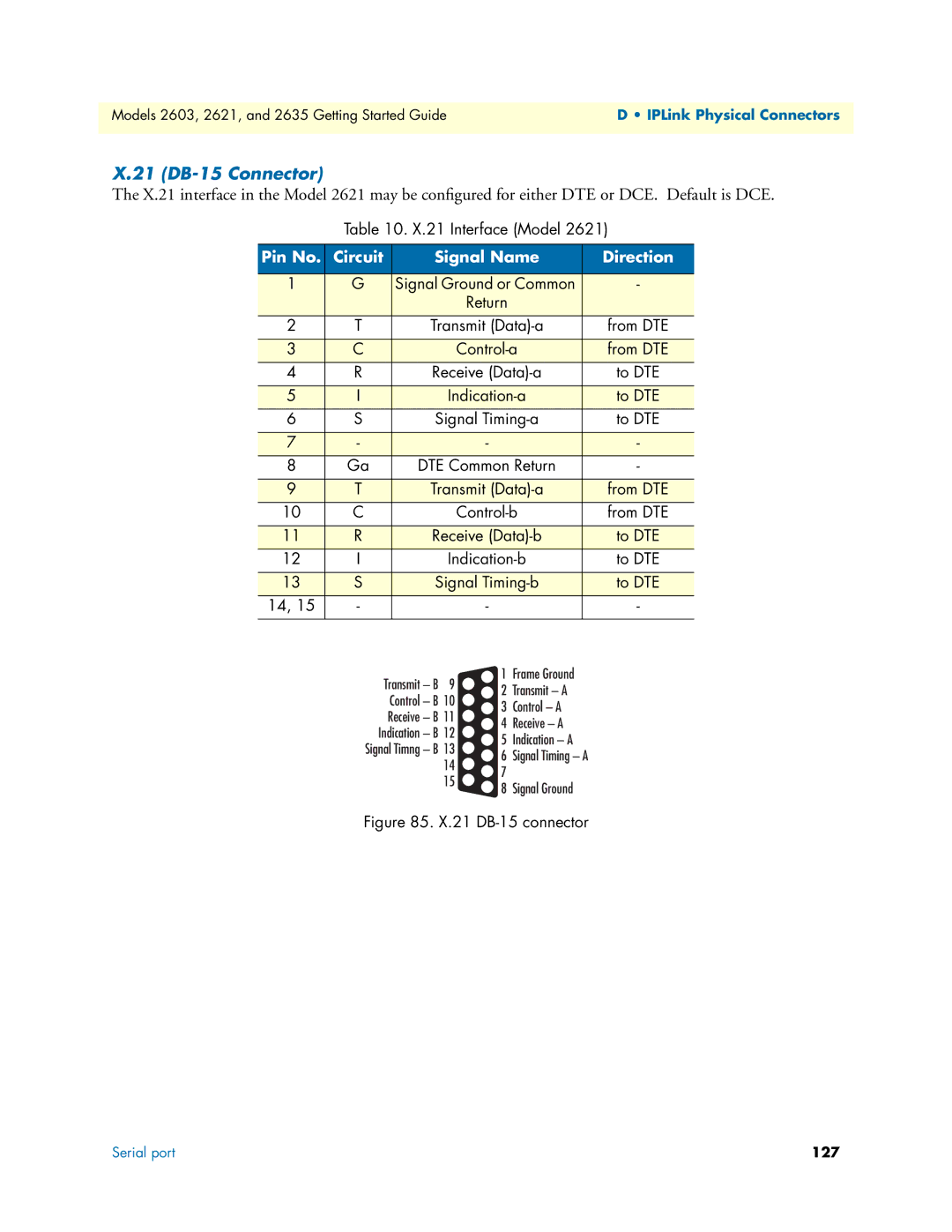
21 DB-15 Connector
Pin No Signal
E1/T1 RJ-48C Connector
Appendix E Command Line Interface CLI Operation
Local VT-100 emulation
Using the Console
CLI Terminology
Produces a list of numbered transport objects
Then
Another example shows when the user must provide a parameter
Adding new users
Administering user accounts
Setting user passwords
Enter the new password twice as prompted
For example, to change the security level for fred, enter
Changing user settings
Controlling login access
Controlling user access