G3. row | Distance between the bottom of the print area on the supply to | ||||
| the bottom of the graphic image. Measured in selected units. | ||||
| English | 0 | - 999 | 203 Dots | 0 - 2029 |
| Metric | 0 | - 2539 | 300 Dots | 0 - 2699 |
The row specified in the constant text, bitmap, line, or box field is added to the row value above to determine the actual position in the format.
G4. column Distance between the left edge of the print area on the supply and the left edge of the graphic. Measured in selected units.
| English | 0 | - 399 | 203 Dots | 0 | - 811 |
| Metric | 0 | - 1015 | 300 Dots | 0 | - 1199 |
| The column specified in the constant text, bitmap, line, or box | |||||
| field is added to the col value above to determine the actual | |||||
| position in the format. |
|
|
| ||
G5. mode | Imaging mode. Enter 0. |
|
|
| ||
G6. rotation | The orientation of the graphic on the supply. Enter 0. | |||||
Example | G,57,0,0,0,0 p |
|
|
| ||
Defines a graphic field that is identified by the number 57. The image begins at 0,0. The imaging mode is 0 and there is no rotation.
S a m p l e B i t m a p G r a p h i c I m a g e
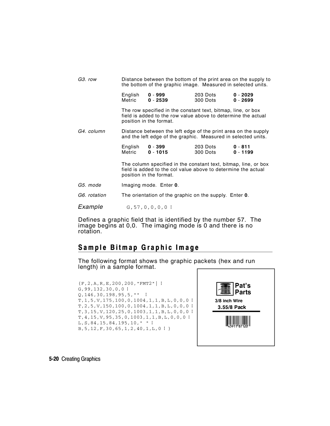
The following format shows the graphic packets (hex and run length) in a sample format.
{F,2,A,R,E,200,200,"FMT2" p G,99,132,30,0,0 p Q,146,30,198,95,5,"" p T,1,5,V,175,100,0,1004,1,1,B,L,0,0,0 p T,2,5,V,150,100,0,1004,1,1,B,L,0,0,0 p T,3,15,V,120,25,0,1003,1,1,B,L,0,0,0 p T,4,15,V,95,35,0,1003,1,1,B,L,0,0,0 p L,S,84,15,84,195,10," " p B,5,12,F,30,65,1,2,40,1,L,0 p }