NOTE: The
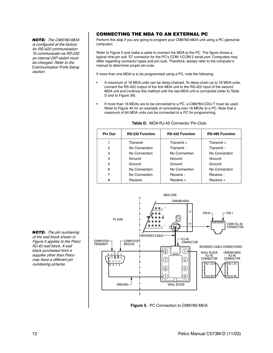
NOTE: The pin numbering of the wall block shown in Figure 5 applies to the Pelco
CONNECTING THE MDA TO AN EXTERNAL PC
Perform this step if you are going to program your
Refer to Figure 5 and make a cable to connect the MDA to the PC. The figure shows a typical
If more than one MDA is to be programmed using a PC, note the following:
¥A maximum of 16 MDA units can be
¥If more than 16 MDAs are to be connected to a PC, a
Table D. MDA RJ-45 Connector Pin-Outs
Pin Out |
|
|
|
|
|
|
|
1 | Transmit | Transmit + | Transmit + |
2 | No Connection | Transmit - | Transmit - |
3 | No Connection | No Connection | No Connection |
4 | Ground | Ground | Ground |
5 | Ground | Ground | Ground |
6 | No Connection | No Connection | No Connection |
7 | No Connection | Receive - | Receive - |
8 | Receive | Receive + | Receive + |
|
|
|
|
|
|
|
|
|
| MDA SIDE |
|
|
| |
|
|
|
|
|
|
|
|
| ||
|
|
|
| 14 | 15 | 16 |
|
| PIN 8 | PIN 1 |
|
|
|
|
|
| PGM |
| 120V A | ||
|
|
|
|
|
|
|
|
| ||
|
|
|
|
|
| MON |
|
|
|
|
|
| PC SIDE |
|
|
|
|
|
| ||
|
|
|
|
|
|
| COM1 | COM2 |
| COM1 |
|
|
|
|
|
|
| UNI T |
|
| CONNECTOR |
|
|
|
|
|
|
|
|
|
| |
|
|
|
| REVERSED CABLE |
|
|
| |||
COMPUTER |
|
|
| COMPUTER |
|
|
|
|
| |
|
|
|
|
|
| CONNECTOR |
|
| ||
TRANSMIT |
|
|
| RECEIVE |
|
|
|
|
| |
|
|
|
|
|
|
| REVERSED CABLE CONNECTIONS | |||
|
|
|
|
|
|
|
|
| ||
5 | 4 | 3 | 2 | 1 |
| 8 |
| 1 | WALL BLOCK | |
|
|
|
| |||||||
|
|
|
|
|
|
|
|
| ||
|
|
|
|
|
| 7 |
| 2 | CONNECTOR | CONNECTOR |
|
|
|
|
|
|
|
|
| ||
9 |
| 8 | 7 | 6 |
|
|
|
| PIN 1=TX | PIN 1=TX |
|
|
|
|
|
|
| ||||
|
|
|
|
|
| 6 |
| 3 |
|
|
|
|
|
|
|
| 5 |
| 4 | PIN 8=RX | PIN 8=RX |
|
|
| GROUND |
|
| WALL BLOCK |
|
| ||
Figure 5. PC Connection to CM9760-MDA
12 | Pelco Manual |
