COMMUNICATION PORTS SETUP
NOTE: COM 1 is config- ured at the factory for
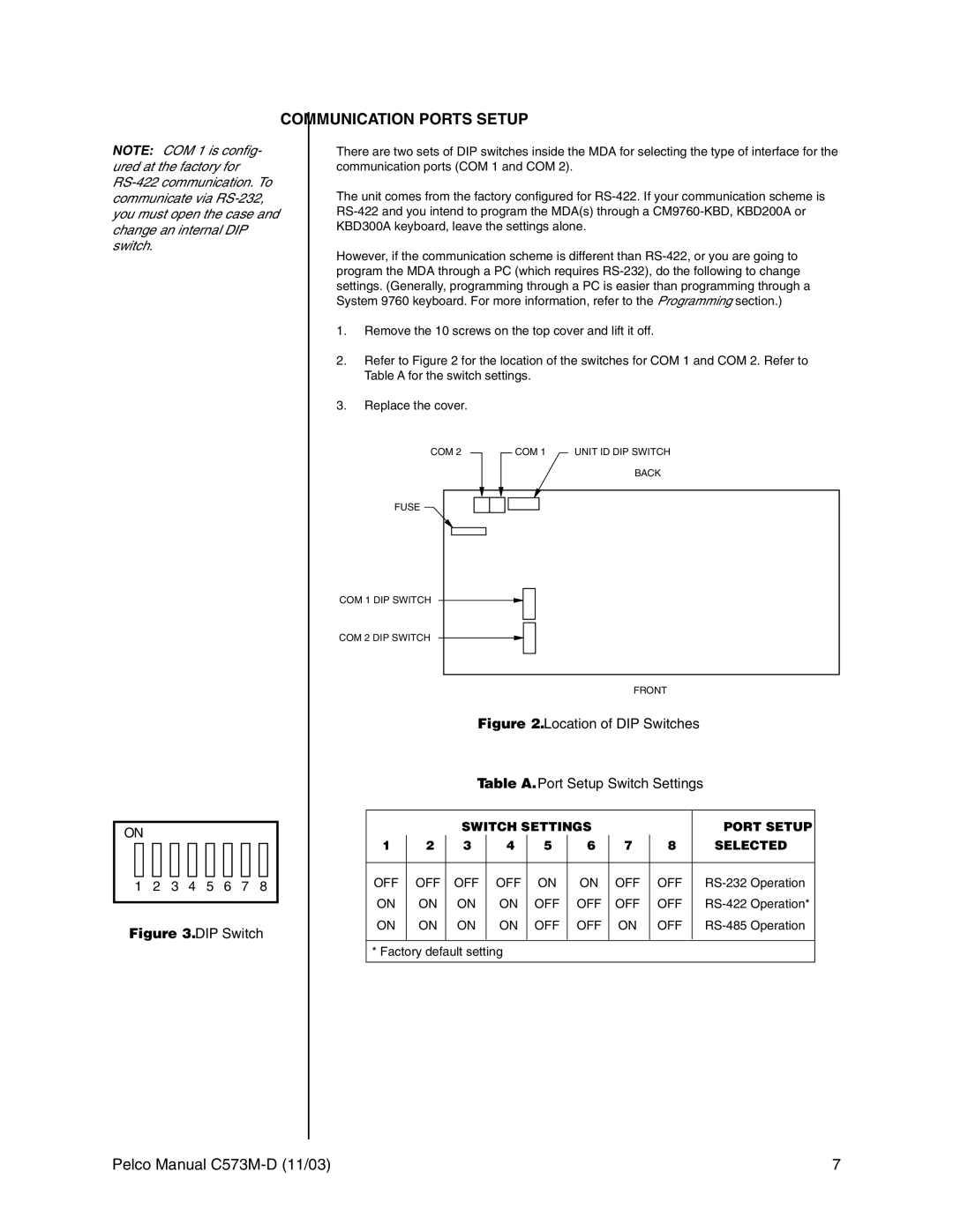
There are two sets of DIP switches inside the MDA for selecting the type of interface for the communication ports (COM 1 and COM 2).
The unit comes from the factory configured for
However, if the communication scheme is different than
1.Remove the 10 screws on the top cover and lift it off.
2.Refer to Figure 2 for the location of the switches for COM 1 and COM 2. Refer to Table A for the switch settings.
3.Replace the cover.
COM 2 |
|
|
| COM 1 |
|
|
FUSE |
COM 1 DIP SWITCH |
COM 2 DIP SWITCH |
UNIT ID DIP SWITCH
BACK
ON
1 2 3 4 5 6 7 8
Figure 3. DIP Switch
FRONT
Figure 2. Location of DIP Switches
Table A. Port Setup Switch Settings
|
| SWITCH SETTINGS |
|
|
| PORT SETUP | |||
1 | 2 | 3 | 4 | 5 |
| 6 | 7 | 8 | SELECTED |
|
|
|
|
|
|
|
|
|
|
OFF | OFF | OFF | OFF | ON |
| ON | OFF | OFF | |
ON | ON | ON | ON | OFF |
| OFF | OFF | OFF | |
ON | ON | ON | ON | OFF |
| OFF | ON | OFF | |
|
|
|
|
|
|
|
|
|
|
* Factory default setting
Pelco Manual | 7 |
