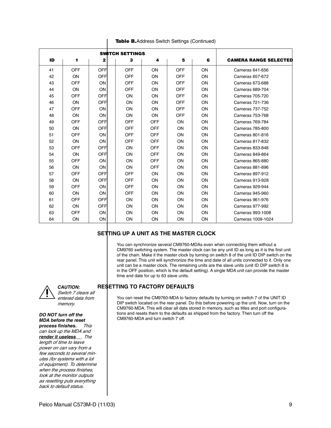
Table B. Address Switch Settings (Continued)
|
|
|
| SWITCH SETTINGS |
|
|
|
|
|
|
| ||
ID |
| 1 |
| 2 |
| 3 |
| 4 |
| 5 |
| 6 | CAMERA RANGE SELECTED |
|
|
|
|
|
| ||||||||
|
|
|
|
|
|
|
|
|
|
|
|
|
|
41 |
| OFF |
| OFF |
| OFF |
| ON |
| OFF |
| ON | Cameras |
42 |
| ON |
| OFF |
| OFF |
| ON |
| OFF |
| ON | Cameras |
43 |
| OFF |
| ON |
| OFF |
| ON |
| OFF |
| ON | Cameras |
44 |
| ON |
| ON |
| OFF |
| ON |
| OFF |
| ON | Cameras |
45 |
| OFF |
| OFF |
| ON |
| ON |
| OFF |
| ON | Cameras |
46 |
| ON |
| OFF |
| ON |
| ON |
| OFF |
| ON | Cameras |
47 |
| OFF |
| ON |
| ON |
| ON |
| OFF |
| ON | Cameras |
48 |
| ON |
| ON |
| ON |
| ON |
| OFF |
| ON | Cameras |
49 |
| OFF |
| OFF |
| OFF |
| OFF |
| ON |
| ON | Cameras |
50 |
| ON |
| OFF |
| OFF |
| OFF |
| ON |
| ON | Cameras |
51 |
| OFF |
| ON |
| OFF |
| OFF |
| ON |
| ON | Cameras |
52 |
| ON |
| ON |
| OFF |
| OFF |
| ON |
| ON | Cameras |
53 |
| OFF |
| OFF |
| ON |
| OFF |
| ON |
| ON | Cameras |
54 |
| ON |
| OFF |
| ON |
| OFF |
| ON |
| ON | Cameras |
55 |
| OFF |
| ON |
| ON |
| OFF |
| ON |
| ON | Cameras |
56 |
| ON |
| ON |
| ON |
| OFF |
| ON |
| ON | Cameras |
57 |
| OFF |
| OFF |
| OFF |
| ON |
| ON |
| ON | Cameras |
58 |
| ON |
| OFF |
| OFF |
| ON |
| ON |
| ON | Cameras |
59 |
| OFF |
| ON |
| OFF |
| ON |
| ON |
| ON | Cameras |
60 |
| ON |
| ON |
| OFF |
| ON |
| ON |
| ON | Cameras |
61 |
| OFF |
| OFF |
| ON |
| ON |
| ON |
| ON | Cameras |
62 |
| ON |
| OFF |
| ON |
| ON |
| ON |
| ON | Cameras |
63 |
| OFF |
| ON |
| ON |
| ON |
| ON |
| ON | Cameras |
64 |
| ON |
| ON |
| ON |
| ON |
| ON |
| ON | Cameras |
|
|
|
|
|
|
|
|
|
|
|
|
|
|
SETTING UP A UNIT AS THE MASTER CLOCK
CAUTION: Switch 7 clears all entered data from memory.
DO NOT turn off the MDA before the reset process finishes. This can lock up the MDA and render it useless. The length of time to leave power on can vary from a few seconds to several min- utes (for systems with a lot of equipment). To determine when the process finishes, look at the monitor outputs as resetting puts everything back to default status.
You can synchronize several
RESETTING TO FACTORY DEFAULTS
You can reset the
Pelco Manual | 9 |
