Installation
1.Remove all of the contents from the shipping box.
2.Install the lens:
NOTE: Megapixel lenses are designed and tested to deliver optimal image quality to megapixel cameras. A standard definition lens installed on a megapixel camera will limit the resolution of the camera and create poor image quality.
a.Make sure the lens does not touch the camera imager when installed.
Screw the lens onto the lens mount. Be careful to prevent dust from entering the space between the lens and the imager. If necessary, use clean, compressed air to remove any foreign matter (refer to the instructions shipped with the lens).
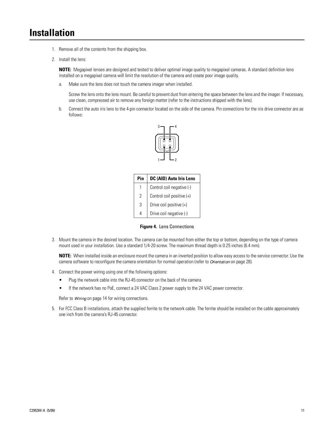
b.Connect the auto iris lens to the
3
4
1
2
Pin | DC (AID) Auto Iris Lens |
|
|
1 | Control coil negative |
2 | Control coil positive (+) |
3 | Drive coil positive (+) |
4 | Drive coil negative |
|
|
Figure 4. Lens Connections
3.Mount the camera in the desired location. The camera can be mounted from either the top or bottom, depending on the type of camera mount used in your installation. Use a standard
NOTE: When installed inside an enclosure mount the camera in an inverted position to allow easy access to the service connector. Use the camera software to reconfigure the camera orientation for normal operation (refer to Orientation on page 28).
4.Connect the power wiring using one of the following options:
•Plug the network cable into the
•If the network has no PoE, connect a 24 VAC Class 2 power supply to the 24 VAC power connector.
Refer to Wiring on page 14 for wiring connections.
5.For FCC Class B installations, attach the supplied ferrite to the network cable. The ferrite should be installed on the cable approximately one inch from the camera’s
11 |