WIRING
CAT5 CABLE
Connect a Cat5 cable to the
NOTE: The camera will autosense and work with either a crossover cable or straight cable.
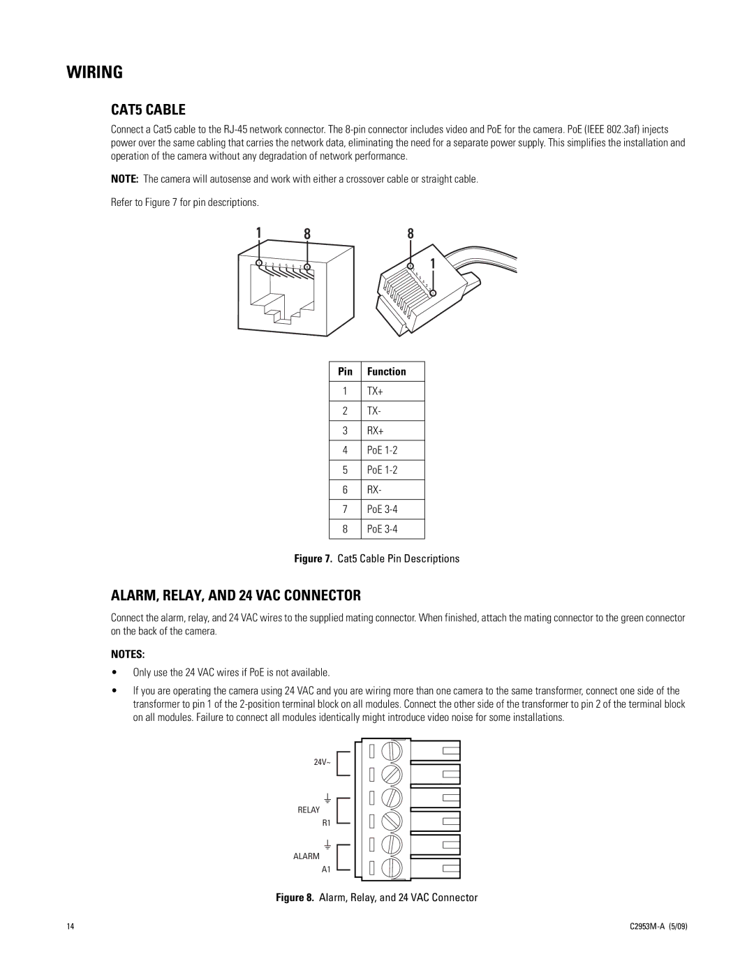
Refer to Figure 7 for pin descriptions.
1 | 8 | 8 |
8 1
7
6
5
4
3
2
1
Pin | Function |
|
|
1 | TX+ |
|
|
2 | TX- |
|
|
3 | RX+ |
|
|
4 | PoE |
|
|
5 | PoE |
|
|
6 | RX- |
|
|
7 | PoE |
|
|
8 | PoE |
|
|
Figure 7. Cat5 Cable Pin Descriptions
ALARM, RELAY, AND 24 VAC CONNECTOR
Connect the alarm, relay, and 24 VAC wires to the supplied mating connector. When finished, attach the mating connector to the green connector on the back of the camera.
NOTES:
•Only use the 24 VAC wires if PoE is not available.
•If you are operating the camera using 24 VAC and you are wiring more than one camera to the same transformer, connect one side of the transformer to pin 1 of the
24V~
RELAY
R1
ALARM
A1
Figure 8. Alarm, Relay, and 24 VAC Connector
14 |
|