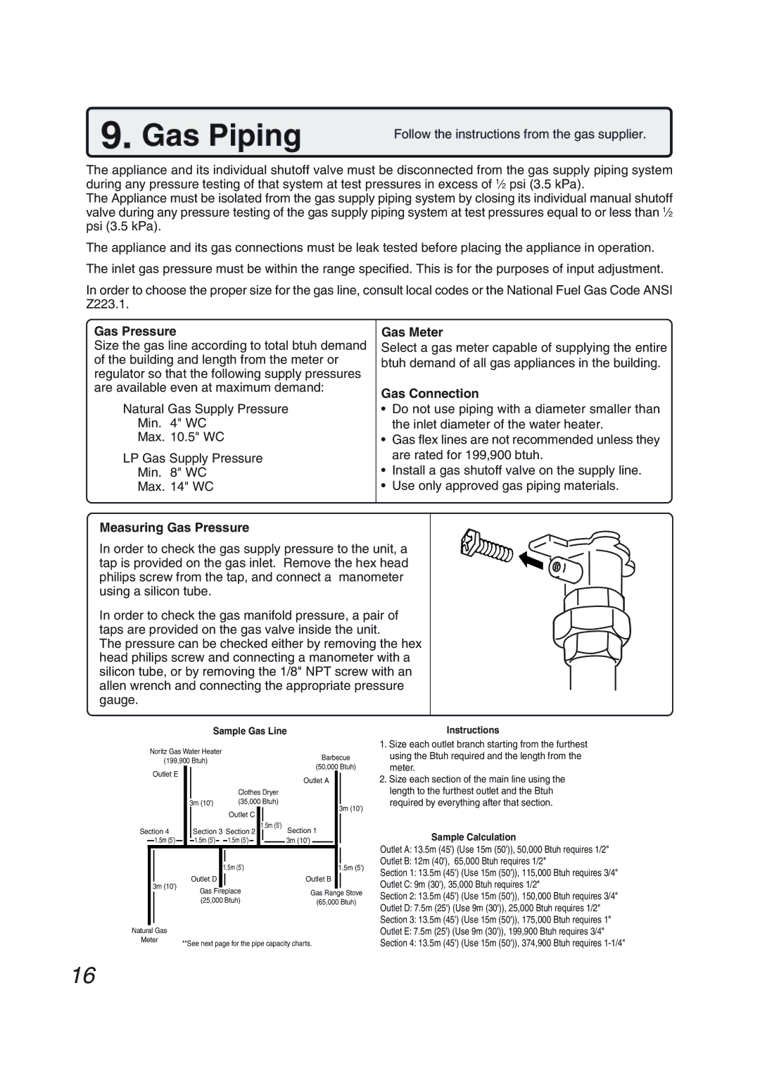
N-0751M-OD, N-0751M specifications
The Pentax N-0751M and N-0751M-OD are advanced digital cameras designed primarily for outdoor and rugged environments. These models exemplify the blend of functionality and durability that Pentax is known for, appealing to both photography enthusiasts and professionals who require reliable equipment in demanding conditions.One of the standout features of the N-0751M and its counterpart, the N-0751M-OD, is their robust construction. Built to withstand harsh environments, these cameras are weather-resistant, ensuring that they can handle rain, dust, and extreme temperatures. This makes them ideal for nature photographers, adventure enthusiasts, and even those who work in challenging conditions.
The N-0751M series is equipped with a high-resolution sensor that captures stunning images with remarkable clarity and detail. The camera features an advanced image processing engine that enhances color accuracy and dynamic range, allowing users to create vibrant and lifelike photos. This sensor also performs exceptionally well in low-light environments, making it versatile for various shooting situations.
Another key characteristic of the N-0751M and N-0751M-OD is their fast and responsive autofocus system. This ensures that users can quickly lock onto their subjects, which is critical for capturing fleeting moments, whether in wildlife photography or action sports. The cameras also come with multiple autofocus modes and options, providing photographers with the flexibility to choose the best setting for their shooting style.
In terms of usability, the N-0751M series features an intuitive interface with customizable settings that allow users to adapt the camera to their personal preferences. The ergonomic design promotes comfort during extended shooting sessions, making it easy to navigate through menus and settings quickly.
For connectivity, the N-0751M and N-0751M-OD come equipped with Wi-Fi capabilities, facilitating easy sharing and remote control through a smartphone app. This enables photographers to transfer images wirelessly and control the camera from a distance, enhancing the shooting experience.
In summary, the Pentax N-0751M and N-0751M-OD embody the perfect combination of durability, image quality, and user-friendly technology. With robust features that cater to professional demands, these cameras stand out as reliable tools for capturing stunning images in any environment. Whether for work or passion, photographers can count on the N-0751M series to deliver superior performance and exceptional results.