Link Interfaces Reference
RS530 To RS449 Conversion Cable
DB25 MALE |
| DB37 MALE/FEMALE | ||||
|
| 2 | Transmitted Data (A) | 4 |
|
|
|
| |||||
|
| 14 | Transmitted Data (B) | 22 |
|
|
|
| 3 | Received Data (A) | 6 |
|
|
|
| 16 | Received Data (B) | 24 |
|
|
|
| 8 | Received Line Signal Detector (A) | 13 |
|
|
|
| 10 | Received Line Signal Detector (B) | 31 |
|
|
|
| 6 | Data Set Ready (A) | 11 |
|
|
|
| 22 | Data Set Ready (B) | 29 |
|
|
|
| 4 | Request to Send (A) | 7 |
|
|
|
| 19 | Request to Send (B) | 25 |
|
|
|
| 5 | Clear to Send (A) | 9 |
|
|
|
| 13 | Clear to Send (B) | 27 |
|
|
|
| 20 | Data Terminal Ready (A) | 12 |
|
|
|
| 23 | Data Terminal Ready (B) | 30 |
|
|
|
| 17 | Receiver Signal Element Timing (DCE Source) (A) | 8 |
|
|
|
| 9 | Receiver Signal Element Timing (DCE Source) (B) | 26 |
|
|
|
| 15 | Transmit Signal Element Timing (DCE Source) (A) | 5 |
|
|
|
| 12 | Transmit Signal Element Timing (DCE Source) (B) | 23 |
|
|
|
| 24 | Transmit Signal Element Timing (DTE Source) (A) | 17 |
|
|
|
| 11 | Transmit Signal Element Timing (DTE Source) (B) | 35 |
|
|
|
| 7 | Signal Ground | 19 |
|
|
|
| 1 | Shield | 1 |
|
|
|
|
|
|
|
|
|
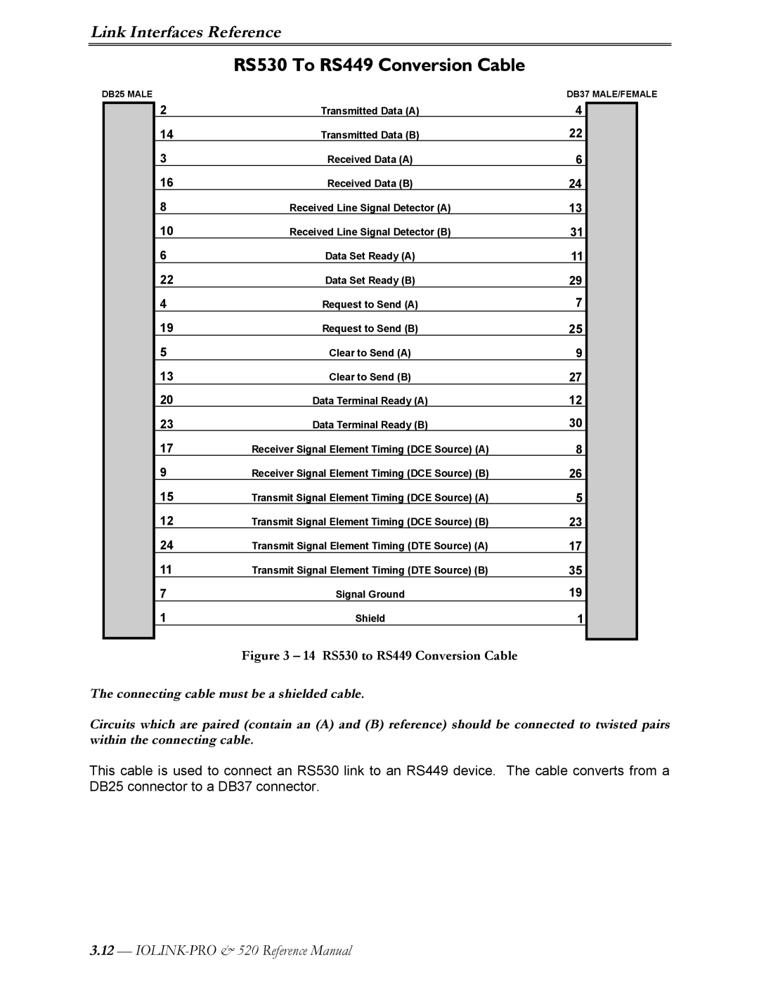
Figure 3 – 14 RS530 to RS449 Conversion Cable
The connecting cable must be a shielded cable.
Circuits which are paired (contain an (A) and (B) reference) should be connected to twisted pairs within the connecting cable.
This cable is used to connect an RS530 link to an RS449 device. The cable converts from a DB25 connector to a DB37 connector.
3.12—