Link Interfaces Reference
RS530 Null-Modem Cable Configuration
DB25 MALE
1Shield
2Transmitted Data (A)
14Transmitted Data (B)
3Received Data (A)
16Received Data (B)
4Request To Send (A)
19Request To Send (B)
5Clear To Send (A)
13Clear To Send (B)
6DCE Ready (A)
22DCE Ready (B)
20DTE Ready (A)
23DTE Ready (B)
7Signal Ground
8Received Line Signal Detector (A)
10Received Line Signal Detector (B)
15Transmit Timing (A) DCE Source
12Transmit Timing (B) DCE Source
24Transmit Timing (A) DTE Source
11Transmit Timing (B) DTE Source
18Local Loopback
21Remote Loopback
17Receiver Timing (A) DCE Source
9Receiver Timing (B) DCE Source
25Test Mode
DB25 MALE
Shield | 1 |
Received Data (A) | 3 |
Received Data (B) 16 | |
Transmitted Data (A) | 2 |
Transmitted Data (B) 14 | |
DCE Ready (A) | 6 |
DCE Ready (B) 22 | |
Clear To Send (A) | 5 |
Clear To Send (B) 13 | |
Request To Send (A) | 4 |
Request To Send (B) 19 | |
Received Line Signal Detector (A) | 8 |
Received Line Signal Detector (B) 10 | |
Signal Ground | 7 |
DTE Ready (A) 20 | |
DTE Ready (B) 23 Receiver Timing (A) DCE Source 17
Receiver Timing (B) DCE Source | 9 |
Transmit Timing (A) DTE Source 24 | |
Transmit Timing (B) DTE Source | 11 |
Local Loopback 18 | |
Remote Loopback | 21 |
Transmit Timing (A) DCE Source 15
Transmit Timing (B) DCE Source 12
Test Mode 25
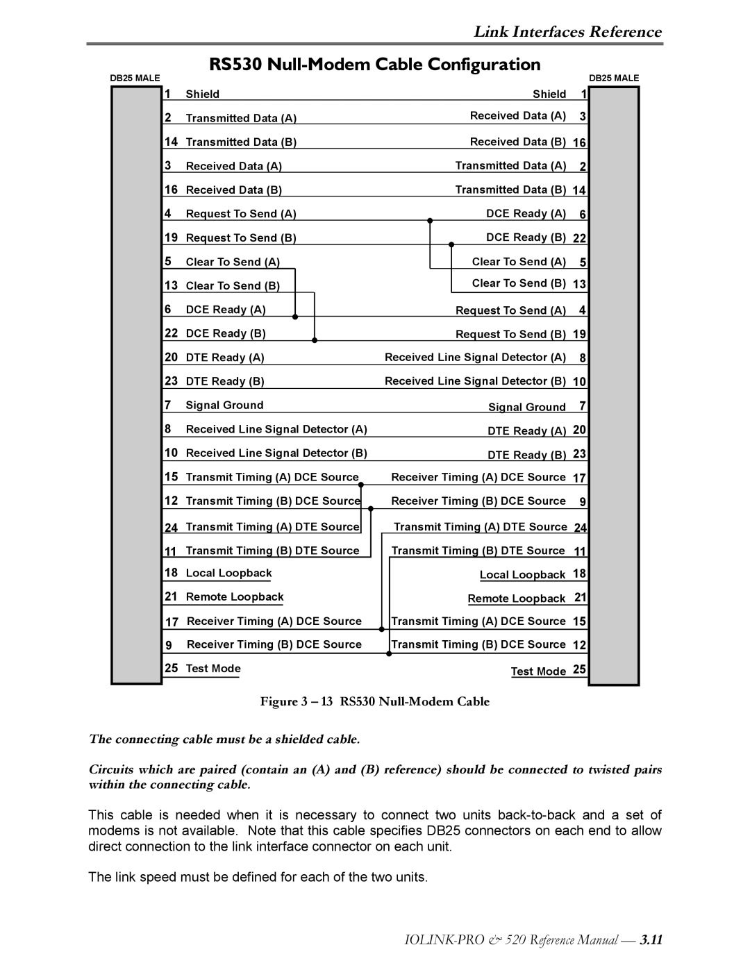
Figure 3 – 13 RS530 Null-Modem Cable
The connecting cable must be a shielded cable.
Circuits which are paired (contain an (A) and (B) reference) should be connected to twisted pairs within the connecting cable.
This cable is needed when it is necessary to connect two units
The link speed must be defined for each of the two units.