ISDN Connection Management
Combination
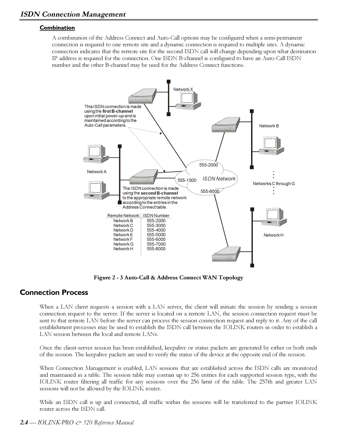
A combination of the Address Connect and
Network X
This ISDN connection is made using the first
Network A
The ISDN connection is made using the
to the appropriate remote network ![]() according to the entries in the
according to the entries in the
Address Connect table.
Remote Network ISDN Number
Network B | |
Network C | |
Network D | |
Network E | |
Network F | |
Network G | |
Network H |
ISDN Network
Network B
Networks C through G
Network H
Figure 2 - 3 Auto-Call & Address Connect WAN Topology
Connection Process
When a LAN client requests a session with a LAN server, the client will initiate the session by sending a session connection request to the server. If the server is located on a remote LAN, the session connection request must be sent to that remote LAN before the server can process the session connection request and reply to it. Any of the call establishment processes may be used to establish the ISDN call between the IOLINK routers in order to establish a LAN session between the local and remote LANs.
Once the
When Connection Management is enabled, LAN sessions that are established across the ISDN calls are monitored and maintained in a table. The session table may contain up to 256 entries for each supported session type, with the IOLINK router filtering all traffic for any sessions over the 256 limit of the table. The 257th and greater LAN sessions will not be allowed by the IOLINK router.
While an ISDN call is up and connected, all traffic within the sessions will be transferred to the partner IOLINK router across the ISDN call.
2.4—
