Introduction
IP Header Details
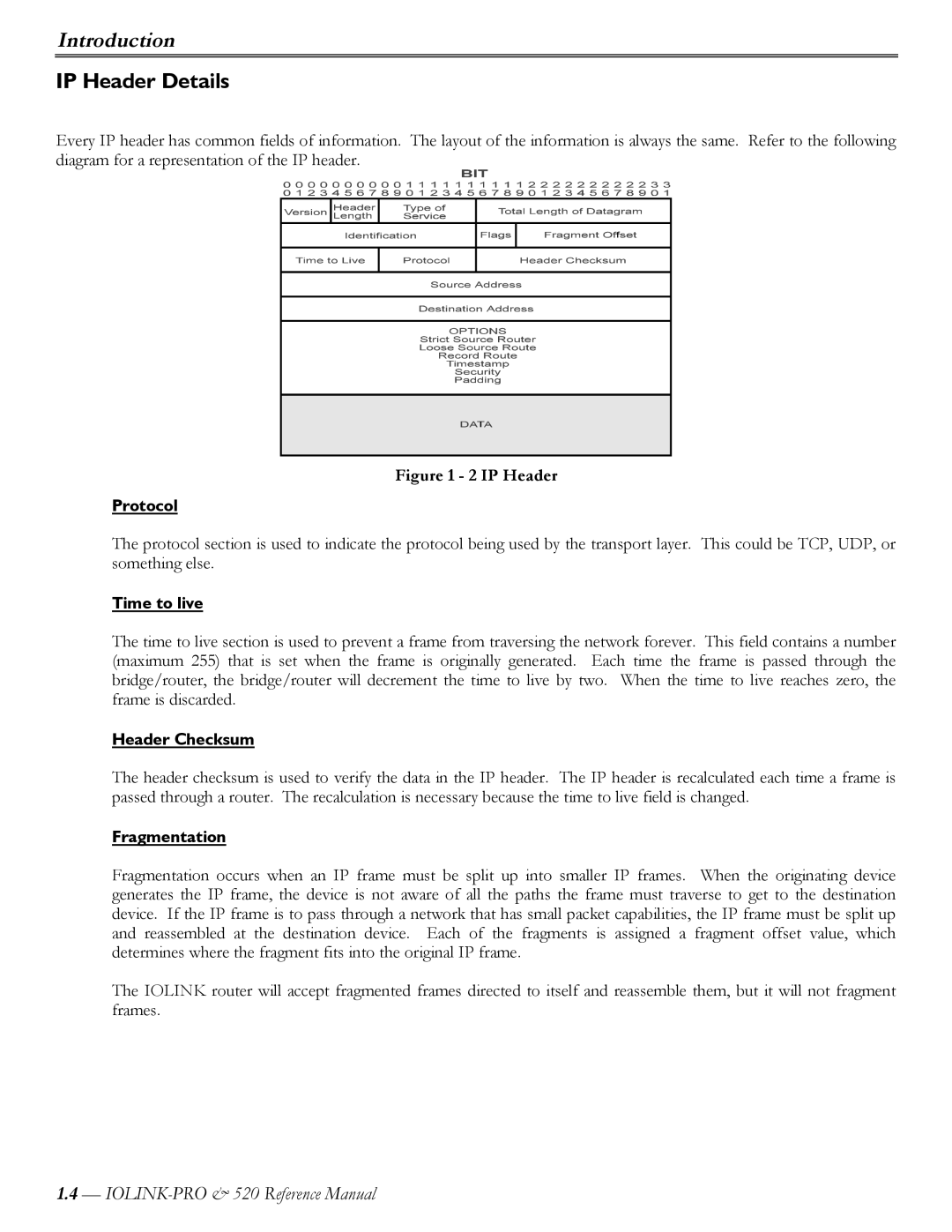
Every IP header has common fields of information. The layout of the information is always the same. Refer to the following diagram for a representation of the IP header.
Figure 1 - 2 IP Header
Protocol
The protocol section is used to indicate the protocol being used by the transport layer. This could be TCP, UDP, or something else.
Time to live
The time to live section is used to prevent a frame from traversing the network forever. This field contains a number (maximum 255) that is set when the frame is originally generated. Each time the frame is passed through the bridge/router, the bridge/router will decrement the time to live by two. When the time to live reaches zero, the frame is discarded.
Header Checksum
The header checksum is used to verify the data in the IP header. The IP header is recalculated each time a frame is passed through a router. The recalculation is necessary because the time to live field is changed.
Fragmentation
Fragmentation occurs when an IP frame must be split up into smaller IP frames. When the originating device generates the IP frame, the device is not aware of all the paths the frame must traverse to get to the destination device. If the IP frame is to pass through a network that has small packet capabilities, the IP frame must be split up and reassembled at the destination device. Each of the fragments is assigned a fragment offset value, which determines where the fragment fits into the original IP frame.
The IOLINK router will accept fragmented frames directed to itself and reassemble them, but it will not fragment frames.
1.4—