Link Interfaces Reference
IOLINK-PRO & 520 Reference Manual —

3.13

V.11/X.21 Null-Modem Cable Configuration
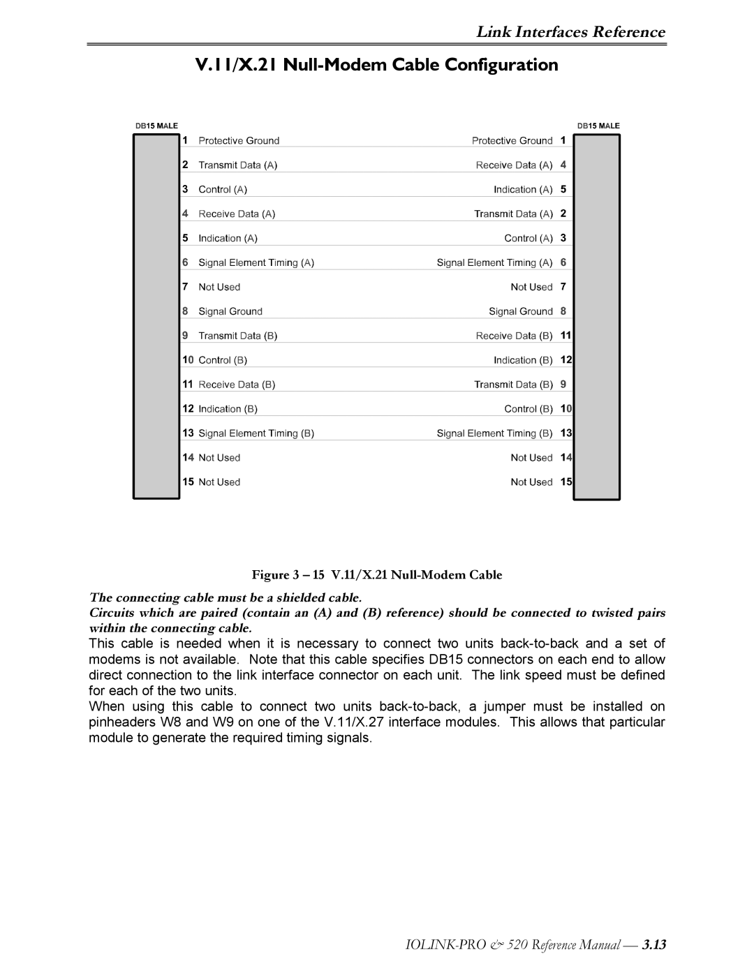
Figure 3 – 15 V.11/X.21 Null-Modem Cable
The connecting cable must be a shielded cable.
Circuits which are paired (contain an (A) and (B) reference) should be connected to twisted pairs
within the connecting cable.
This cable is needed when it is necessary to connect two units back-to-back and a set of
modems is not available. Note that this cable specifies DB15 connectors on each end to allow
direct connection to the link interface connector on each unit. The link speed must be defined
for each of the two units.
When using this cable to connect two units back-to-back, a jumper must be installed on
pinheaders W8 and W9 on one of the V.11/X.27 interface modules. This allows that particular
module to generate the required timing signals.