Philips Semiconductors
Magnetoresistive sensors for
magnetic field measurement
General
sinφ = | Hy | |
Hx | ||
Ho | ||
+ | ||
| cosφ |
Ux = ρ⊥l | ⎛ L | ⎞ ⎛ | 1 + | ⎛ Δρ⎞ ⎛ | 1 | ⎛ Hy⎞ 2⎞⎞ | ||
| ⎠ ⎝ | – | ⎠⎠ | |||||
| ⎝ wt⎠ ⎝ |
| ⎝ ρ |
| ⎝ H0⎠ | |||
resistance-field (R-H) dependence, so a simple
(6)magnetoresistive element cannot be used directly for linear field measurements. A magnetic biasing field can be used to solve this problem, but a better solution is linearization using
(7)such as for angle measurement. In this case, the direction of the magnetization is parallel to the field and the sensor signal can be described by a cos2α function.
Uy = ρ⊥l | ⎛ 1⎞ ⎛ Δρ⎞ ⎛ Hy⎞ | 1 |
| ⁄ H | ) | 2 | (8) | ||||
⎠ | y |
| |||||||||
| ⎝ t | ⎠ ⎝ ρ | ⎠ ⎝ H |
|
| 0 |
|
|
| ||
|
|
| 0 |
|
|
|
|
|
|
|
|
(Note: if Hx = 0, then H0 must be replaced by H0 + Hx/cos φ).
Neglecting the constant part in Ux, there are two main differences between Ux and Uy:
1.The magnetoresistive signal Ux depends on the square of Hy/H0, whereas the Hall voltage Uy is linear for Hy « H0.
2.The ratio of their maximum values is L/w; the Hall voltage is much smaller as in most cases L » w.
Magnetization of the thin layer
The magnetic field is in reality slightly more complicated than given in equation (6). There are two solutions for angle φ:
φ1 < 90˚ and φ2 > 90˚ (with φ1 + φ2 = 180˚ for Hx = 0).
Replacing φ by 180˚ - φ has no influence on Ux except to change the sign of the Hall voltage and also that of most linearized magnetoresistive sensors.
Therefore, to avoid ambiguity either a short pulse of a proper field in the
Sensors with inclined elements
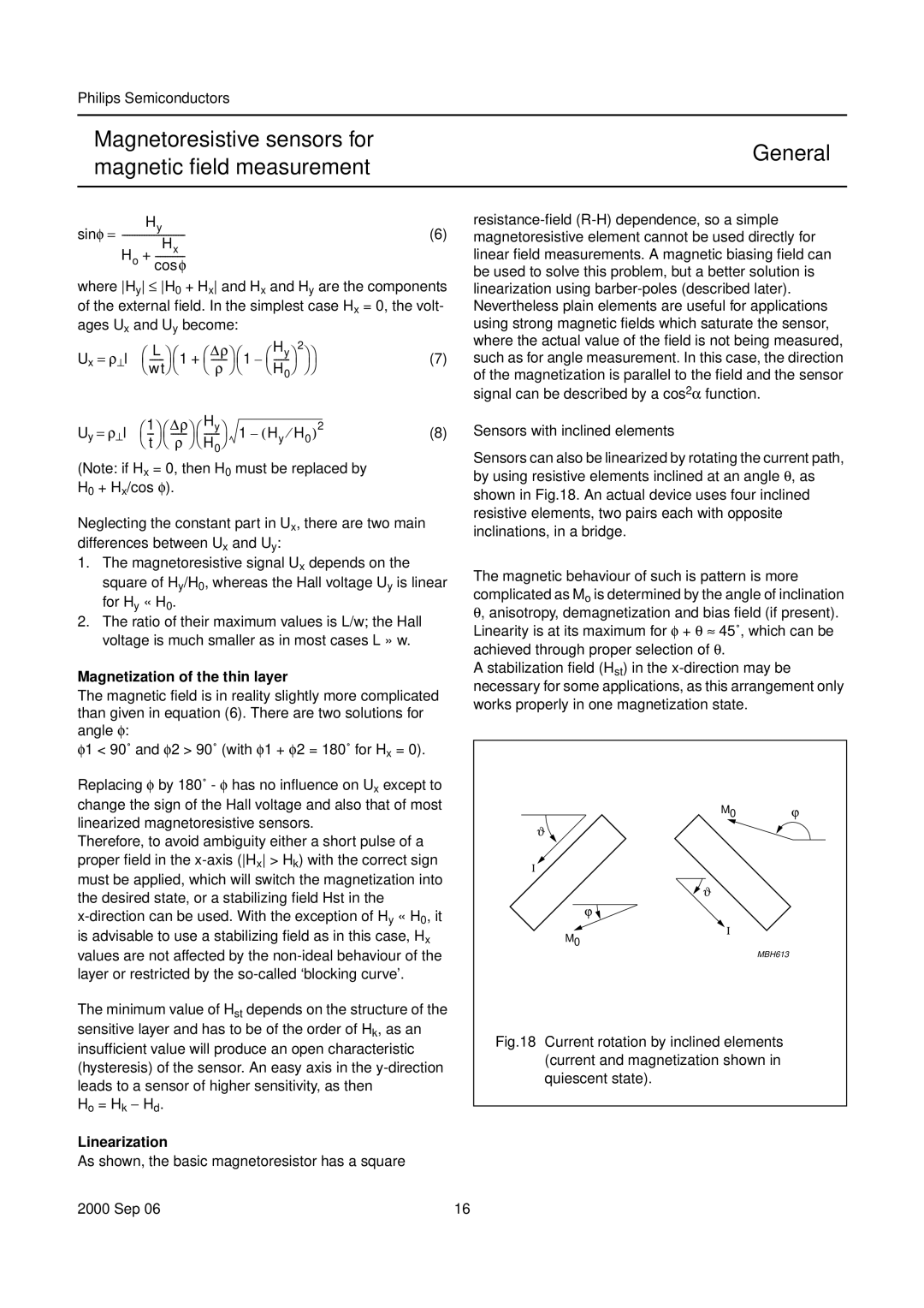
Sensors can also be linearized by rotating the current path, by using resistive elements inclined at an angle θ, as shown in Fig.18. An actual device uses four inclined resistive elements, two pairs each with opposite inclinations, in a bridge.
The magnetic behaviour of such is pattern is more complicated as Mo is determined by the angle of inclination θ, anisotropy, demagnetization and bias field (if present). Linearity is at its maximum for φ + θ ≈ 45˚, which can be achieved through proper selection of θ.
A stabilization field (Hst) in the
handbook, halfpage | M0 | ϕ |
ϑ |
|
|
Ι
![]() ϑ
ϑ
ϕ ![]()
is advisable to use a stabilizing field as in this case, Hx values are not affected by the
M0
Ι
MBH613
The minimum value of Hst depends on the structure of the sensitive layer and has to be of the order of Hk, as an insufficient value will produce an open characteristic (hysteresis) of the sensor. An easy axis in the
Ho = Hk − Hd.
Fig.18 Current rotation by inclined elements (current and magnetization shown in quiescent state).
Linearization
As shown, the basic magnetoresistor has a square
2000 Sep 06 | 16 |