Philips Semiconductors
Magnetoresistive sensors for
magnetic field measurement
Further information for advanced users
THE MR EFFECT
General
In sensors employing the MR effect, the resistance of the |
| ||||
sensor under the influence of a magnetic field changes as |
| ||||
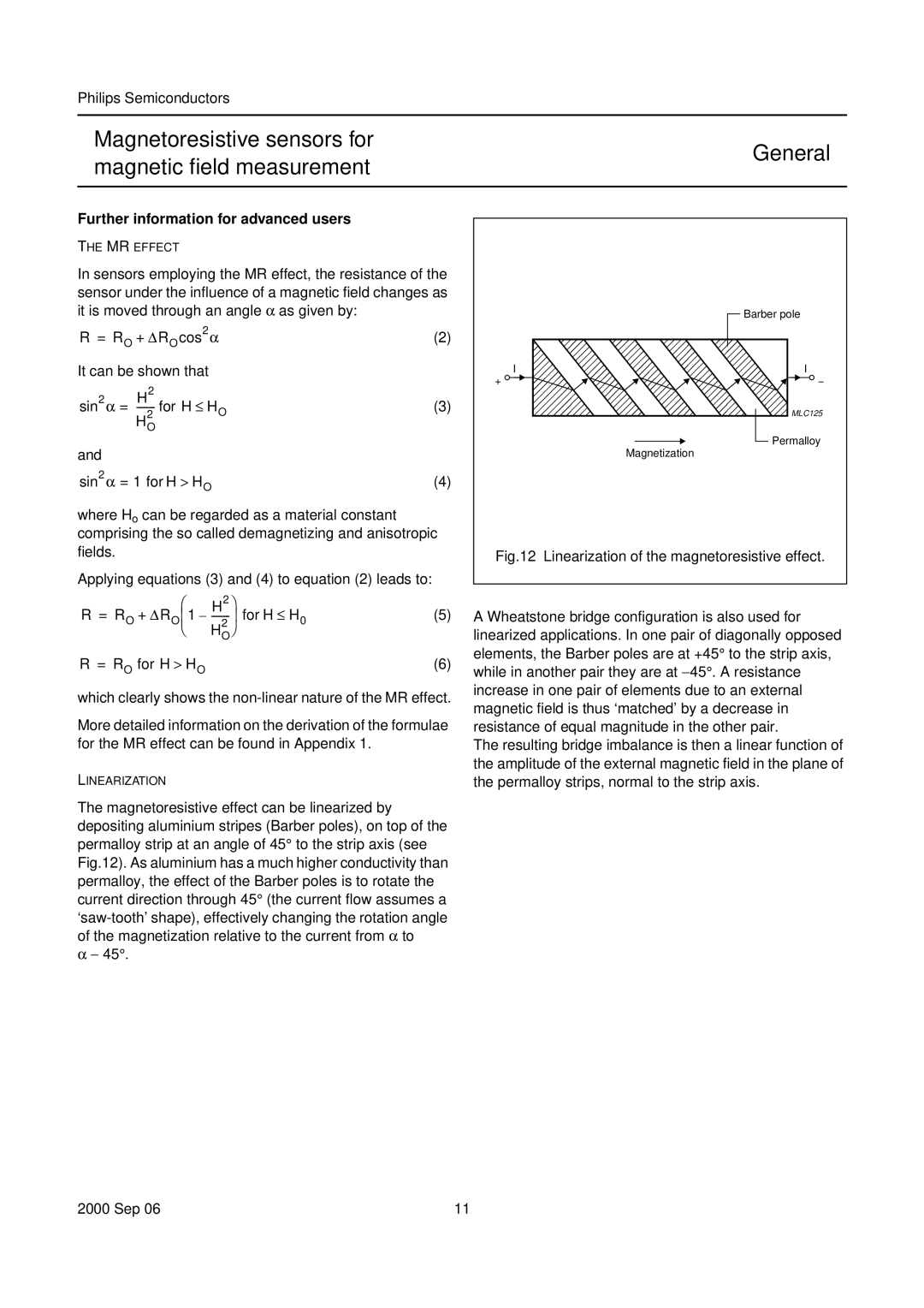
it is moved through an angle α as given by: | handbook, halfpage | Barber pole | |||
R = RO + ΔRO cos2 α |
| ||||
(2) |
| ||||
It can be shown that | I | I | |||
sin | 2 | α = | H2 | (3) |
|
| MLC125 | ||||
|
|
| HO2 |
|
|
and |
|
|
| Permalloy | |
|
|
| Magnetization | ||
sin2 α = 1 for H > HO | (4) |
| |||
where Ho can be regarded as a material constant |
|
comprising the so called demagnetizing and anisotropic |
|
fields. | Fig.12 Linearization of the magnetoresistive effect. |
|
Applying equations (3) and (4) to equation (2) leads to:
R | = RO | ⎛ | H2 ⎞ | (5) | A Wheatstone bridge configuration is also used for |
+ ΔRO ⎜1 | |||||
|
| ⎝ | H2 ⎠ |
| linearized applications. In one pair of diagonally opposed |
|
|
| O |
| |
R = RO for H > HO | (6) | elements, the Barber poles are at +45° to the strip axis, | |||
while in another pair they are at −45°. A resistance | |||||
increase in one pair of elements due to an external magnetic field is thus ‘matched’ by a decrease in resistance of equal magnitude in the other pair.
The resulting bridge imbalance is then a linear function of the amplitude of the external magnetic field in the plane of the permalloy strips, normal to the strip axis.
11
