Philips Semiconductors
Magnetoresistive sensors for
magnetic field measurement
General
A number of Philips’ magnetoresistive sensors use a
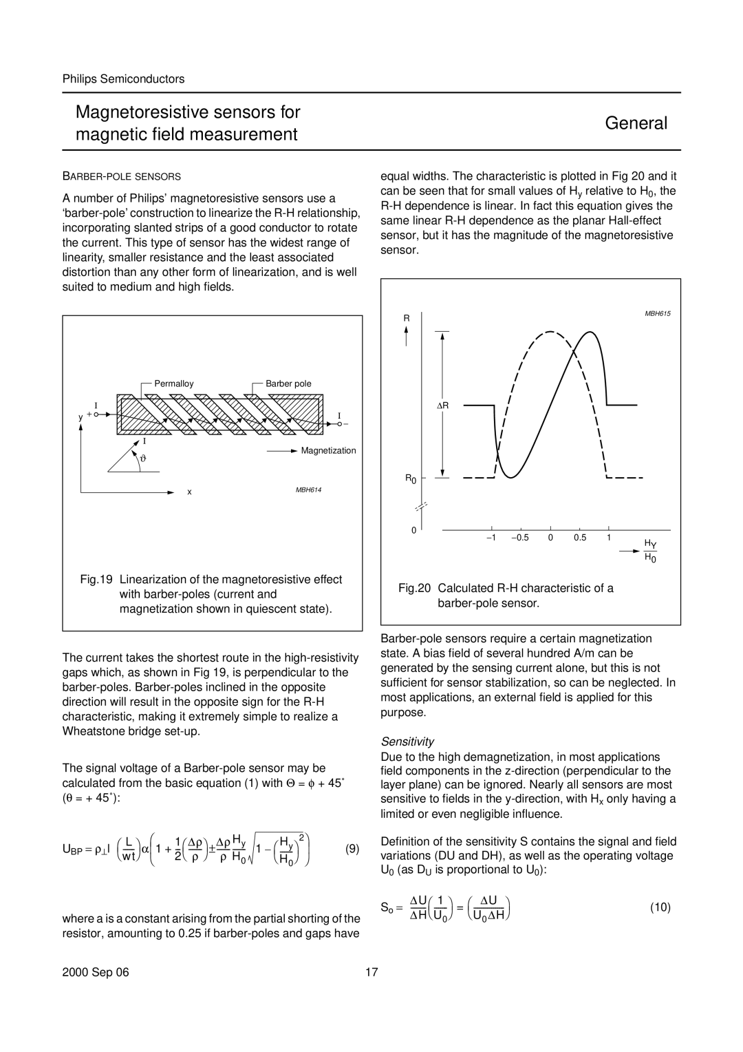
equal widths. The characteristic is plotted in Fig 20 and it can be seen that for small values of Hy relative to H0, the
handbook, halfpage | Permalloy | Barber pole |
|
y + Ι |
| Ι | − |
|
|
| |
| Ι |
|
|
handbook,R halfpage
ΔR
MBH615
ϑ
Magnetization
R0
x | MBH614 |
Fig.19 Linearization of the magnetoresistive effect with barber-poles (current and magnetization shown in quiescent state).
The current takes the shortest route in the high-resistivity gaps which, as shown in Fig 19, is perpendicular to the barber-poles. Barber-poles inclined in the opposite direction will result in the opposite sign for the R-H characteristic, making it extremely simple to realize a Wheatstone bridge set-up.
The signal voltage of a Barber-pole sensor may be calculated from the basic equation (1) with Θ = φ + 45˚ (θ = + 45˚):
0 |
|
|
|
|
|
|
|
|
|
|
|
|
|
|
|
|
|
|
|
|
|
|
|
|
|
| |
| −1 | −0.5 | 0 | 0.5 | 1 |
|
| HY | |||||
|
|
|
| ||||||||||
|
|
|
|
|
|
|
|
|
|
|
| ||
|
|
|
|
|
|
|
|
|
|
|
| H0 |
|
Fig.20 Calculated R-H characteristic of a barber-pole sensor.
Barber-pole sensors require a certain magnetization state. A bias field of several hundred A/m can be generated by the sensing current alone, but this is not sufficient for sensor stabilization, so can be neglected. In most applications, an external field is applied for this purpose.
Sensitivity
Due to the high demagnetization, in most applications field components in the
UBP = ρ⊥l | ⎛ | L | ⎞ | ⎛ | 1 | ⎛ | Δρ⎞ | Δρ Hy | 1 | ⎛ Hy⎞ | 2⎞ | |||
⎝ | ⎠ | α⎜1 | + | ⎝ | – |
| ⎟ | |||||||
| wt | ⎝ | 2 | ρ | ⎠ | ρ H0 |
|
| ⎠ | ⎠ | ||||
|
|
|
|
|
| ⎝ H | ||||||||
|
|
|
|
|
|
|
|
|
|
|
| 0 |
|
|
(9)
Definition of the sensitivity S contains the signal and field variations (DU and DH), as well as the operating voltage U0 (as DU is proportional to U0):
So = | ΔU⎛ 1 | ⎞ | = | ⎛ | ΔU ⎞ | (10) |
| ⎝ | |||||
where a is a constant arising from the partial shorting of the | ΔH⎝ U0⎠ |
|
| |||
resistor, amounting to 0.25 if
2000 Sep 06 | 17 |