Philips Semiconductors
Magnetoresistive sensors for
magnetic field measurement
General
The influence of other disturbing fields can also be eliminated provided they are well known, by adding a second current source to the compensating coil. Such fields might be those arising from the
The brief summary in Table 3 compares the types of compensation and their effects, so they can be assessed for their suitability in a given application. Because these options encompass a range of costs, the individual requirements of an application should be carefully analysed in terms of the performance gains versus relative costs.
|
| CLOCK |
FLIPPING | LF | |
WITH | ||
SOURCE |
| SUPRESSION |
| LC | OF OFFSET |
PHASE-
SENSITIVE
DEMODULATOR
CURRENT
REGULATOR
VOLTAGE & CURRENT
OUTPUT
MBH619
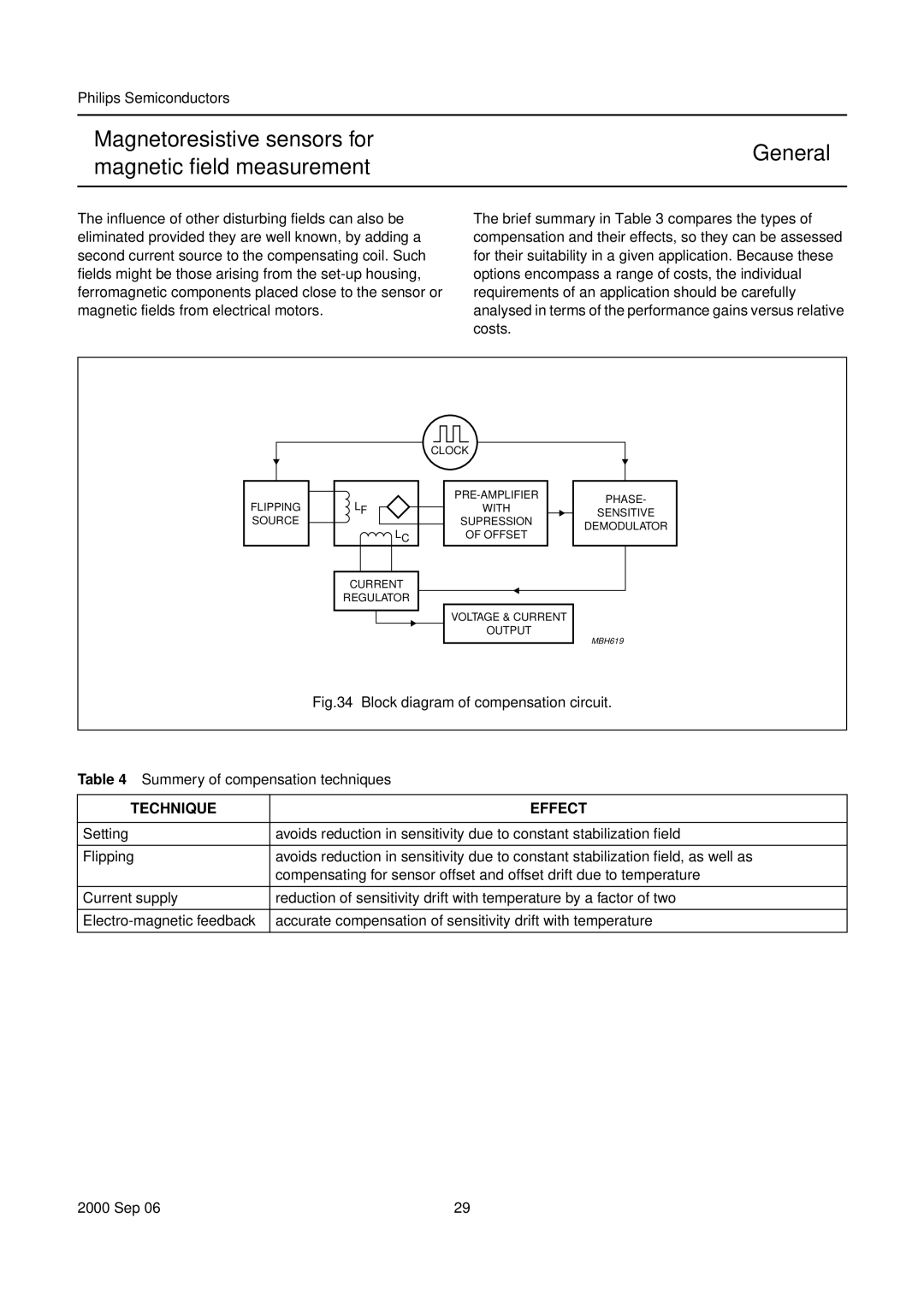
Fig.34 Block diagram of compensation circuit.
Table 4 Summery of compensation techniques
TECHNIQUE | EFFECT |
|
|
Setting | avoids reduction in sensitivity due to constant stabilization field |
|
|
Flipping | avoids reduction in sensitivity due to constant stabilization field, as well as |
| compensating for sensor offset and offset drift due to temperature |
|
|
Current supply | reduction of sensitivity drift with temperature by a factor of two |
|
|
accurate compensation of sensitivity drift with temperature | |
|
|
2000 Sep 06 | 29 |