Philips Semiconductors
Magnetoresistive sensors for
magnetic field measurement
General
| current |
| pulses |
sensor | H y |
| VO |
| Hx |
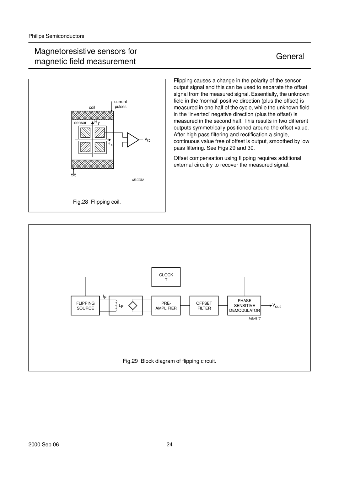
Flipping causes a change in the polarity of the sensor output signal and this can be used to separate the offset signal from the measured signal. Essentially, the unknown field in the ‘normal’ positive direction (plus the offset) is measured in one half of the cycle, while the unknown field in the ‘inverted’ negative direction (plus the offset) is measured in the second half. This results in two different outputs symmetrically positioned around the offset value. After high pass filtering and rectification a single, continuous value free of offset is output, smoothed by low pass filtering. See Figs 29 and 30.
Offset compensation using flipping requires additional external circuitry to recover the measured signal.
MLC762
Fig.28 Flipping coil.
FLIPPING SOURCE
IF
LF
CLOCK
T
PRE-
AMPLIFIER
OFFSET
FILTER
PHASE
SENSITIVE
DEMODULATOR
![]() Vout
Vout
MBH617
Fig.29 Block diagram of flipping circuit.
2000 Sep 06 | 24 |
