DEVICE PARAMETERS
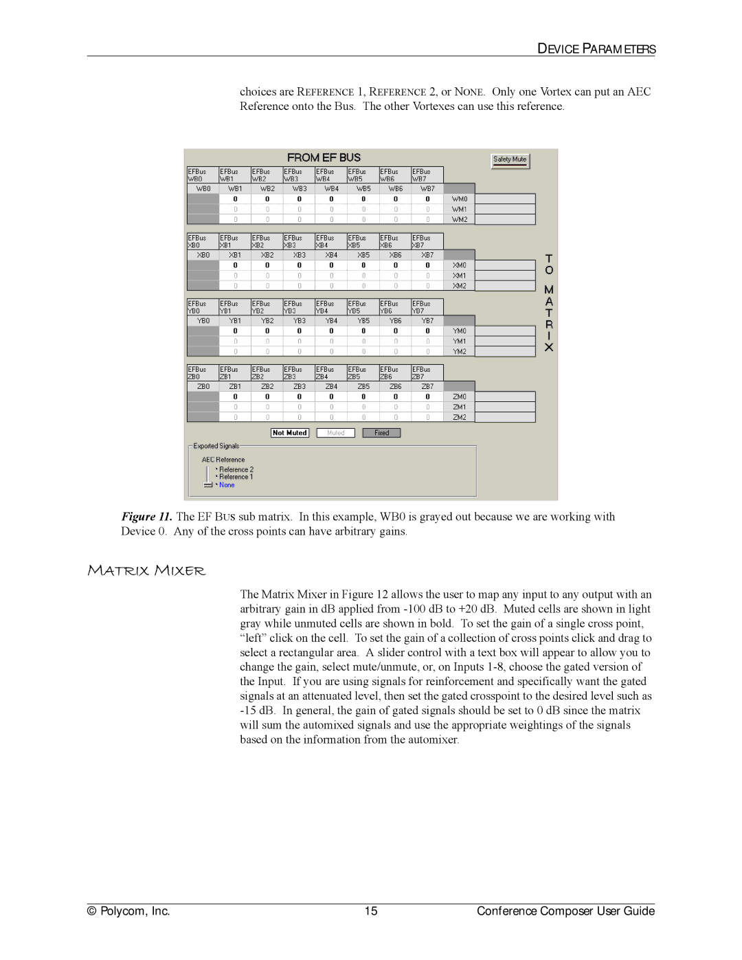
choices are REFERENCE 1, REFERENCE 2, or NONE. Only one Vortex can put an AEC Reference onto the Bus. The other Vortexes can use this reference.
Figure 11. The EF BUS sub matrix. In this example, WB0 is grayed out because we are working with Device 0. Any of the cross points can have arbitrary gains.
MATRIX MIXER
The Matrix Mixer in Figure 12 allows the user to map any input to any output with an arbitrary gain in dB applied from -100 dB to +20 dB. Muted cells are shown in light gray while unmuted cells are shown in bold. To set the gain of a single cross point, “left” click on the cell. To set the gain of a collection of cross points click and drag to select a rectangular area. A slider control with a text box will appear to allow you to change the gain, select mute/unmute, or, on Inputs 1-8, choose the gated version of the Input. If you are using signals for reinforcement and specifically want the gated signals at an attenuated level, then set the gated crosspoint to the desired level such as -15 dB. In general, the gain of gated signals should be set to 0 dB since the matrix will sum the automixed signals and use the appropriate weightings of the signals based on the information from the automixer.
© Polycom, Inc. | 15 | Conference Composer User Guide |