DEVICE PARAMETERS
and a mono mix of the left and right program audio. The program audio is attenuated by 3 dB before adding it into the R1 output.
OUTPUT FILTERS
Each of the outputs can have up to 5 filters of equalization. These filters include Parametric, Low Pass, High Pass, Low Shelf, and High Shelf. To use the filters, select the type of filter and adjust the controls for the filter. You can adjust the con- trols in a variety of ways: by typing in values in the text boxes, using the cursor up/ down, using Page Up/Page Down, or by clicking and holding the knob and moving the mouse up to increase the value or down to decrease the value. The frequency response of the plots may be viewed by clicking on the GRAPH button.
The ENABLE button per filter enables/disables that particular filter on the Output. The ENABLE FILTERS button enables/disables all filters on the particular Output Channel. This button toggles with the Filter Bypass buttons per Output. All filters for a partic- ular output can be bypassed by clicking the BYPASS button.
Once the settings are configured for Output Channel 1, the user may copy those set- tings to all other channels using the COPY CHANNEL 1 FILTERS TO ALL CHANNELS button.
OUTPUTS
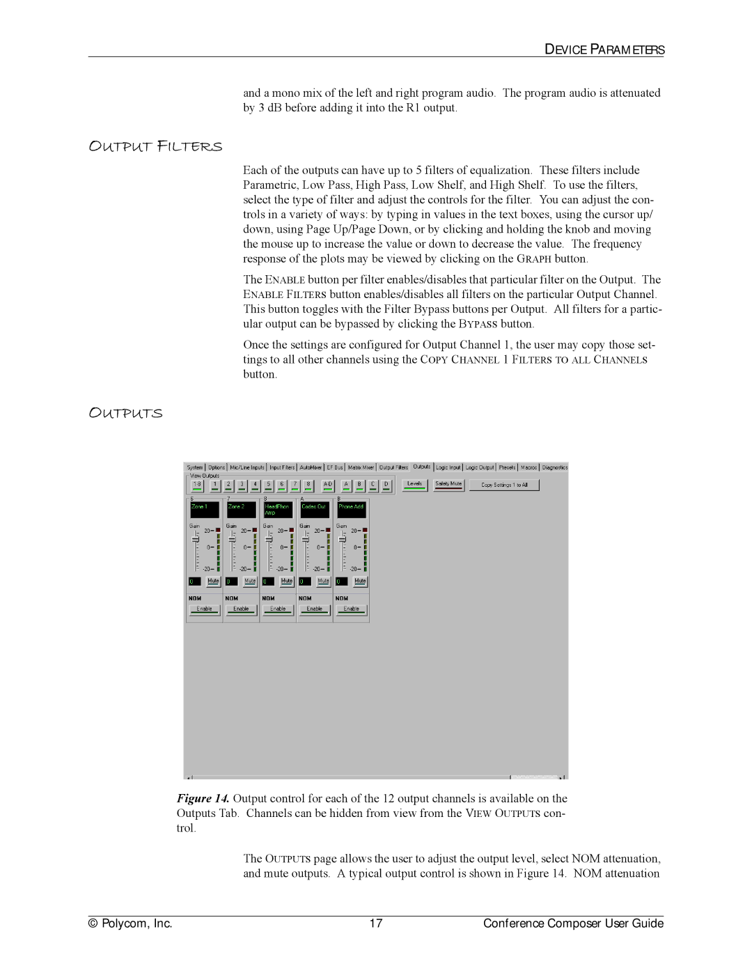
Figure 14. Output control for each of the 12 output channels is available on the Outputs Tab. Channels can be hidden from view from the VIEW OUTPUTS con- trol.
The OUTPUTS page allows the user to adjust the output level, select NOM attenuation, and mute outputs. A typical output control is shown in Figure 14. NOM attenuation
© Polycom, Inc. | 17 | Conference Composer User Guide |
