DEVICE PARAMETERS
MIC/LINE INPUTS
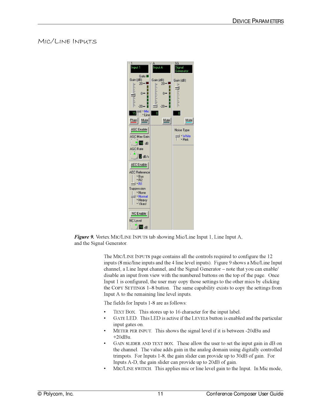
Figure 9. Vortex MIC/LINE INPUTS tab showing Mic/Line Input 1, Line Input A, and the Signal Generator.
The MIC/LINE INPUTS page contains all the controls required to configure the 12 inputs (8 mic/line inputs and the 4 line level inputs). Figure 9 shows a Mic/Line Input channel, a Line Input channel, and the Signal Generator – note that you can enable/ disable an input from view with the numbered buttons on the top of the page. Once Input 1 is configured, the user may copy those settings to the other mics by clicking the COPY SETTINGS 1–8 button. The same capability exists to copy the settings from Input A to the remaining line level inputs.
The fields for Inputs 1-8 are as follows:
•TEXT BOX. This stores up to 16 character for the input label.
•GATE LED. This LED is active if the LEVELS button is enabled and the particular input gates on.
•METER PER INPUT. This shows the signal level if it is between -20dBu and +20dBu.
•GAIN SLIDER AND TEXT BOX. These allow the user to set the input gain in dB on the channel. The value adds gain in the analog domain using digitally controlled trimpots. For Inputs 1-8, the gain slider can provide up to 30dB of gain. For Inputs A-D, the gain slider can provide up to 20dB of gain.
•MIC/LINE SWITCH. This applies mic or line level gain to the Input. In Mic mode,
© Polycom, Inc. | 11 | Conference Composer User Guide |