Site Preparation
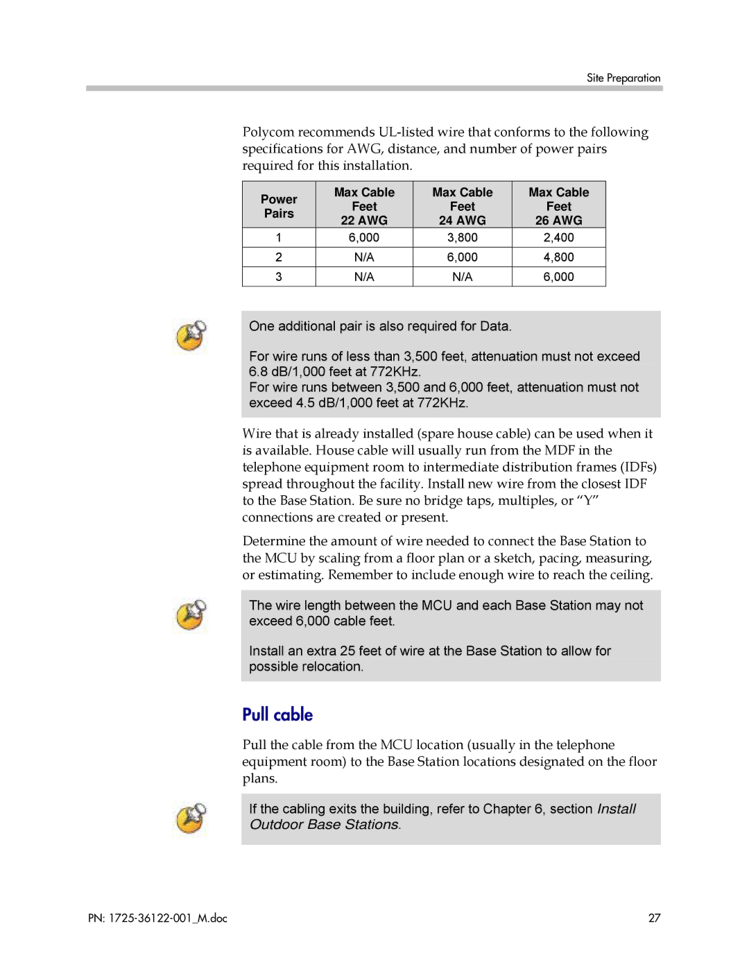
Polycom recommends
| Power |
|
| Max Cable |
|
| Max Cable |
| Max Cable |
|
|
| Feet |
|
| Feet |
| Feet | |
| Pairs |
|
|
|
|
| |||
|
|
| 22 AWG |
|
| 24 AWG |
| 26 AWG | |
|
|
|
|
|
|
| |||
1 |
| 6,000 |
| 3,800 |
| 2,400 | |||
2 |
|
| N/A | 6,000 |
| 4,800 | |||
3 |
|
| N/A |
| N/A | 6,000 | |||
|
|
|
|
|
|
|
|
|
|
One additional pair is also required for Data.
For wire runs of less than 3,500 feet, attenuation must not exceed 6.8 dB/1,000 feet at 772KHz.
For wire runs between 3,500 and 6,000 feet, attenuation must not exceed 4.5 dB/1,000 feet at 772KHz.
Wire that is already installed (spare house cable) can be used when it is available. House cable will usually run from the MDF in the telephone equipment room to intermediate distribution frames (IDFs) spread throughout the facility. Install new wire from the closest IDF to the Base Station. Be sure no bridge taps, multiples, or “Y” connections are created or present.
Determine the amount of wire needed to connect the Base Station to the MCU by scaling from a floor plan or a sketch, pacing, measuring, or estimating. Remember to include enough wire to reach the ceiling.
The wire length between the MCU and each Base Station may not exceed 6,000 cable feet.
Install an extra 25 feet of wire at the Base Station to allow for possible relocation.
Pull cable
Pull the cable from the MCU location (usually in the telephone equipment room) to the Base Station locations designated on the floor plans.
If the cabling exits the building, refer to Chapter 6, section Install Outdoor Base Stations.
PN: | 27 |