Note: Full instructions are provided in the Filling Loop Kit pack.
| 10.0 Installation | ||
|
|
|
|
|
|
|
|
10.3 | Fitting the Filling Loop Kit | ||
1. The filling loop kit supplied with the boiler can be | |||
connected to the taps on the wall plate at this point. | |||
(Either one of two types of loop kit will be supplied - | |||
both function in the same way, differing only in detail). | |||
2. The filling loop is to be connected between the mains | |||
cold water inlet and central heating return isolation taps. | |||
3. The loop and valves must be connected as described | |||
in the instructions supplied with it. | |||
4. Note the orientation of the flow direction arrows on | |||
the stop valve and double check/stop valves. | |||
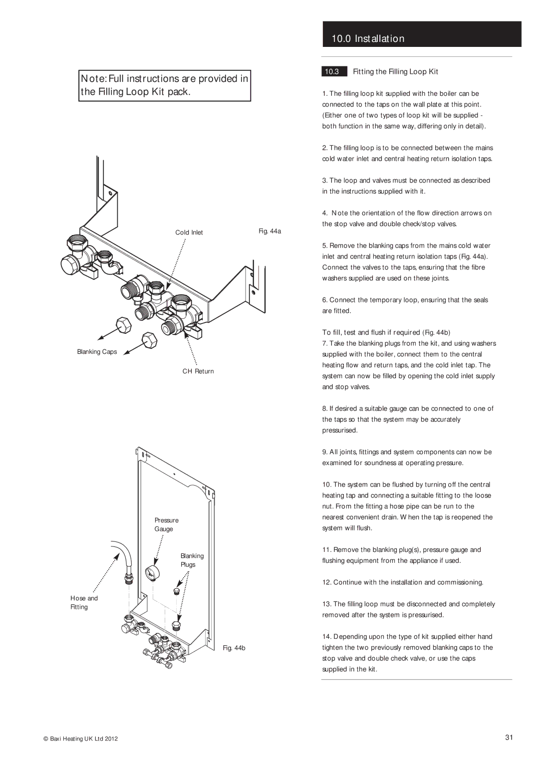
Blanking Caps
Hose and
Fitting
Cold Inlet | Fig. 44a |
CH Return
Pressure
Gauge
Blanking
Plugs
5. Remove the blanking caps from the mains cold water |
inlet and central heating return isolation taps (Fig. 44a). |
Connect the valves to the taps, ensuring that the fibre |
washers supplied are used on these joints. |
6. Connect the temporary loop, ensuring that the seals |
are fitted. |
To fill, test and flush if required (Fig. 44b)
7. Take the blanking plugs from the kit, and using washers | |
supplied with the boiler, connect them to the central | |
heating flow and return taps, and the cold inlet tap. The | |
system can now be filled by opening the cold inlet supply | |
and stop valves. | |
8. If desired a suitable gauge can be connected to one of | |
the taps so that the system may be accurately | |
pressurised. | |
9. All joints, fittings and system components can now be | |
examined for soundness at operating pressure. | |
10. | The system can be flushed by turning off the central |
heating tap and connecting a suitable fitting to the loose | |
nut. From the fitting a hose pipe can be run to the | |
nearest convenient drain. When the tap is reopened the | |
system will flush. | |
11. | Remove the blanking plug(s), pressure gauge and |
flushing equipment from the appliance if used. | |
12. | Continue with the installation and commissioning. |
13. | The filling loop must be disconnected and completely |
removed after the system is pressurised. | |
14. | Depending upon the type of kit supplied either hand |
Fig. 44b
tighten the two previously removed blanking caps to the |
stop valve and double check valve, or use the caps |
supplied in the kit. |
© Baxi Heating UK Ltd 2012 | 31 |