Burner
Sensing Electrode
|
|
| ± | 1 |
| . | 5 |
| |
7 |
|
| ||
|
|
|
|
![]()
![]() 5 .
5 . ![]()
![]()
![]()
![]() 0
0 ![]()
![]()
![]()
![]()
![]()
![]()
![]()
![]()
![]()
![]()
![]()
![]()
![]()
![]()
![]()
![]()
![]() ±
±
4
Viewing Window
Spark Ignition
Electrode

 10 ±1
10 ±1
|
| 13.0 Servicing | ||
|
|
|
|
|
|
|
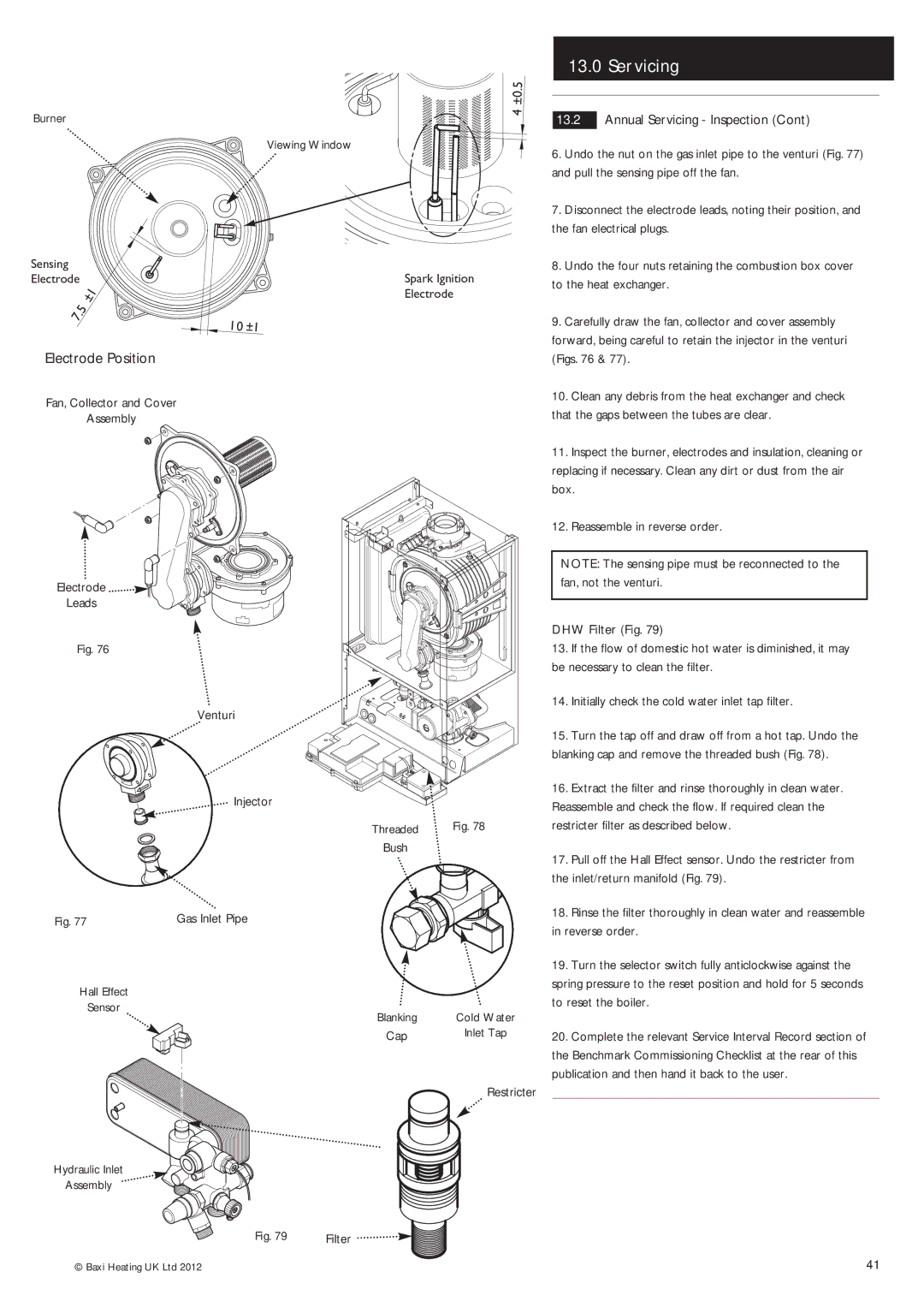
| Annual Servicing - Inspection (Cont) | |
13.2 | ||||
6. | Undo the nut on the gas inlet pipe to the venturi (Fig. 77) | |||
and pull the sensing pipe off the fan. | ||||
7. | Disconnect the electrode leads, noting their position, and | |||
the fan electrical plugs. | ||||
8. | Undo the four nuts retaining the combustion box cover | |||
to the heat exchanger. | ||||
9. | Carefully draw the fan, collector and cover assembly | |||
forward, being careful to retain the injector in the venturi | ||||
Electrode Position
Fan, Collector and Cover
Assembly
Electrode ![]()
![]()
![]()
Leads
Fig. 76
Venturi
![]() Injector
Injector
| Threaded | Fig. 78 |
| Bush |
|
Fig. 77 | Gas Inlet Pipe |
|
Hall Effect |
|
|
Sensor | Blanking | Cold Water |
| ||
| Cap | Inlet Tap |
Restricter
Hydraulic Inlet
Assembly
Fig. 79 | Filter |
(Figs. 76 & 77). | |
10. | Clean any debris from the heat exchanger and check |
that the gaps between the tubes are clear. | |
11. | Inspect the burner, electrodes and insulation, cleaning or |
replacing if necessary. Clean any dirt or dust from the air | |
box. | |
12. | Reassemble in reverse order. |
NOTE: The sensing pipe must be reconnected to the fan, not the venturi.
DHW Filter (Fig. 79)
13.If the flow of domestic hot water is diminished, it may be necessary to clean the filter.
14.Initially check the cold water inlet tap filter.
15.Turn the tap off and draw off from a hot tap. Undo the blanking cap and remove the threaded bush (Fig. 78).
16.Extract the filter and rinse thoroughly in clean water. Reassemble and check the flow. If required clean the restricter filter as described below.
17.Pull off the Hall Effect sensor. Undo the restricter from the inlet/return manifold (Fig. 79).
18.Rinse the filter thoroughly in clean water and reassemble in reverse order.
19.Turn the selector switch fully anticlockwise against the spring pressure to the reset position and hold for 5 seconds to reset the boiler.
20.Complete the relevant Service Interval Record section of the Benchmark Commissioning Checklist at the rear of this publication and then hand it back to the user.
© Baxi Heating UK Ltd 2012 | 41 |