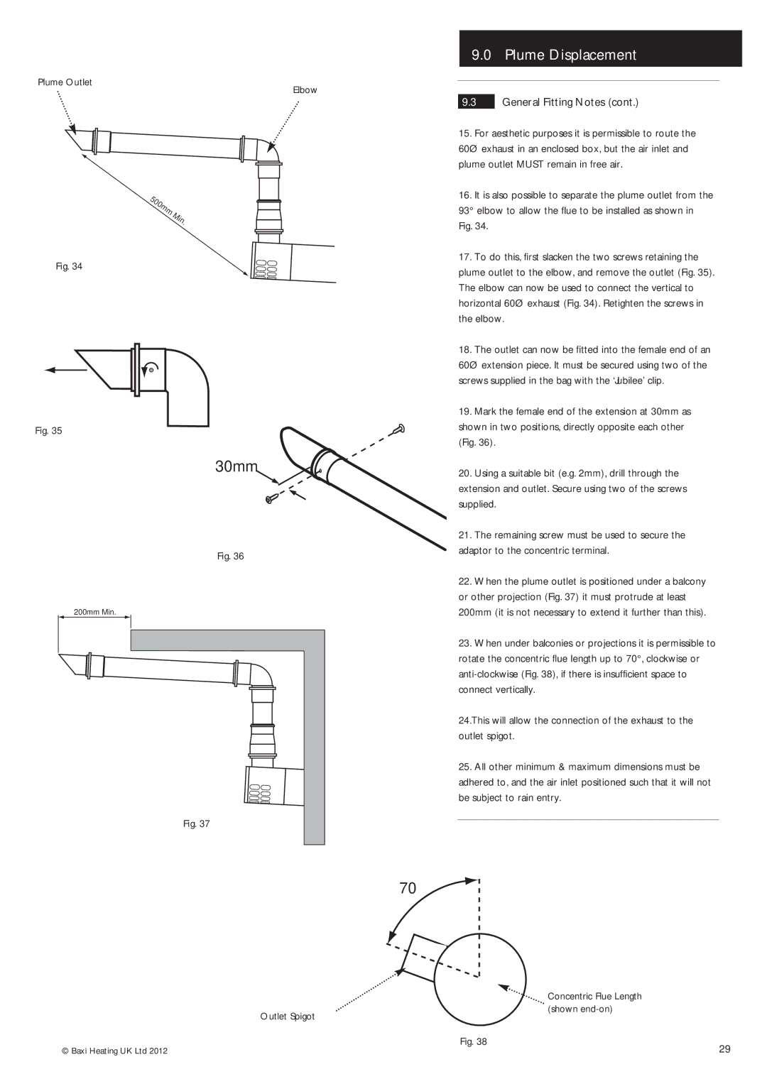
Plume Outlet
Fig. 34
Fig. 35
Elbow
| 9.0 |
| Plume Displacement | |
|
|
|
|
|
|
|
|
|
|
9.3 |
| General Fitting Notes (cont.) | ||
15. For aesthetic purposes it is permissible to route the | ||||
60Ø exhaust in an enclosed box, but the air inlet and | ||||
plume outlet MUST remain in free air. | ||||
16. It is also possible to separate the plume outlet from the | ||||
93° elbow to allow the flue to be installed as shown in | ||||
Fig. 34. |
|
| ||
17. To do this, first slacken the two screws retaining the | ||||
plume outlet to the elbow, and remove the outlet (Fig. 35). | ||||
The elbow can now be used to connect the vertical to | ||||
horizontal 60Ø exhaust (Fig. 34). Retighten the screws in | ||||
the elbow. | ||||
18. The outlet can now be fitted into the female end of an | ||||
60Ø extension piece. It must be secured using two of the | ||||
screws supplied in the bag with the ‘Jubilee’ clip. | ||||
19. Mark the female end of the extension at 30mm as | ||||
shown in two positions, directly opposite each other | ||||
(Fig. 36). |
|
| ||
30mm
Fig. 36
200mm Min.
Fig. 37
20. | Using a suitable bit (e.g. 2mm), drill through the |
extension and outlet. Secure using two of the screws | |
supplied. | |
21. | The remaining screw must be used to secure the |
adaptor to the concentric terminal. | |
22. | When the plume outlet is positioned under a balcony |
or other projection (Fig. 37) it must protrude at least | |
200mm (it is not necessary to extend it further than this). | |
23. | When under balconies or projections it is permissible to |
rotate the concentric flue length up to 70°, clockwise or | |
| |
connect vertically. | |
24.This will allow the connection of the exhaust to the outlet spigot.
25.All other minimum & maximum dimensions must be adhered to, and the air inlet positioned such that it will not be subject to rain entry.
70°
Outlet Spigot
Concentric Flue Length ![]() (shown
(shown
© Baxi Heating UK Ltd 2012 | Fig. 38 | 29 |
|
