4.Use a gauge to carefully measure the distance from miter slot to straight edge. Take measurements at both front and back of table – these should be the same.
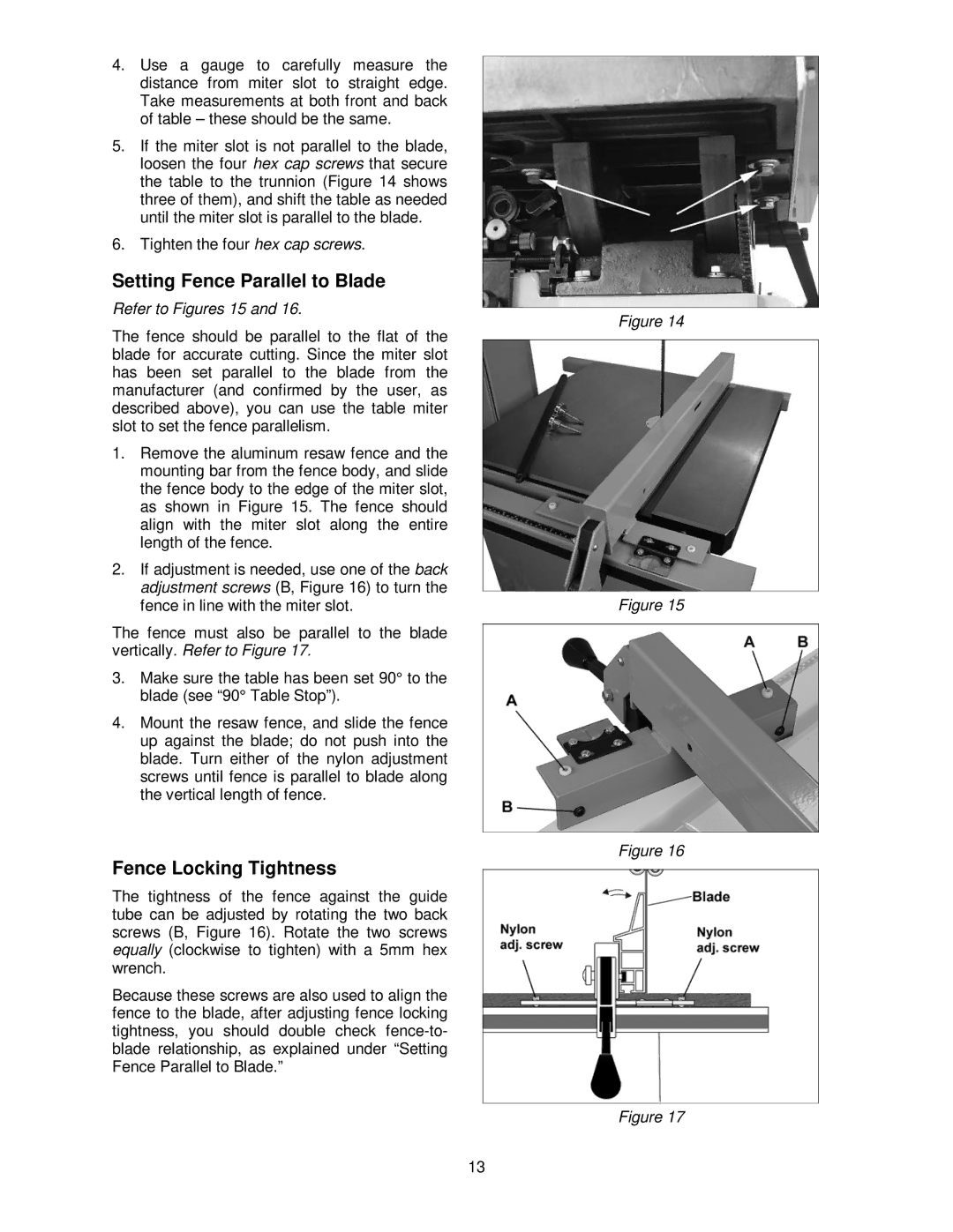
5.If the miter slot is not parallel to the blade, loosen the four hex cap screws that secure the table to the trunnion (Figure 14 shows three of them), and shift the table as needed until the miter slot is parallel to the blade.
6.Tighten the four hex cap screws.
Setting Fence Parallel to Blade
Refer to Figures 15 and 16.
Figure 14
The fence should be parallel to the flat of the blade for accurate cutting. Since the miter slot has been set parallel to the blade from the manufacturer (and confirmed by the user, as described above), you can use the table miter slot to set the fence parallelism.
1.Remove the aluminum resaw fence and the mounting bar from the fence body, and slide the fence body to the edge of the miter slot, as shown in Figure 15. The fence should align with the miter slot along the entire length of the fence.
2.If adjustment is needed, use one of the back adjustment screws (B, Figure 16) to turn the
fence in line with the miter slot. | Figure 15 |
The fence must also be parallel to the blade |
|
vertically. Refer to Figure 17. |
|
3.Make sure the table has been set 90° to the blade (see “90° Table Stop”).
4.Mount the resaw fence, and slide the fence up against the blade; do not push into the blade. Turn either of the nylon adjustment screws until fence is parallel to blade along the vertical length of fence.
Figure 16
Fence Locking Tightness
The tightness of the fence against the guide tube can be adjusted by rotating the two back screws (B, Figure 16). Rotate the two screws equally (clockwise to tighten) with a 5mm hex wrench.
Because these screws are also used to align the fence to the blade, after adjusting fence locking tightness, you should double check
Figure 17
13