The
1.Loosen the socket head cap screw (E, Figure 29) and push the thrust bearing bracket laterally to desired position.
2.
3.Loosen the locking screw (F) and push the thrust bearing up to the back of the blade.
4.Adjust the thrust bearing until the space between the thrust bearing surface (or groove bottom) and the back edge of the blade is approximately 0.015” (1/64”). On the
5.Tighten locking screw (F).
6.Make sure all locking screws on the upper guide bearing assembly are tightened when adjustments are finished.
Lower Blade Guides
Refer to Figure 33.
1.Disconnect band saw from power source.
2.Open lower door and lower blade guard.
3.Adjust the lower guide bearings and lower thrust bearing below the table, using the same procedure and measurements as for the upper guide bearings and upper thrust bearing described above.
Movement summary: Loosen locking lever
(G)to move guide bracket using dial (H). Loosen knob (J) to rotate side bearings, using (K) and (L). Loosen locking screw (M) to slide thrust bearing toward blade.
4.Make sure all screws, knobs and lever are tightened when adjustments are complete.
NOTE: The locking lever (G, Figure 33) can be
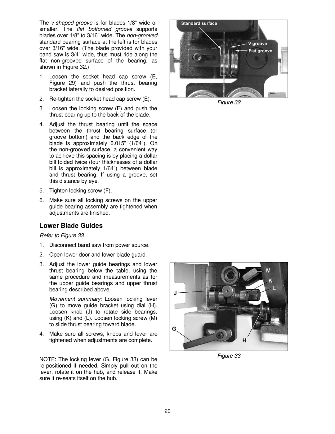
Figure 32
Figure 33
20