9.Make further adjustments as needed, with the saw disconnected from power.
Upper Blade Guides
The bearing guides should be set so that contact between blade and guides will occur only when the blade is under pressure from a workpiece. To adjust the upper bearing guides for proper blade control, proceed as follows.
Refer to Figures 28 through 31.
1.Disconnect machine from power source.
2.Blade must already be tensioned and tracking correctly. Place quick tension lever in “Full Tension” position.
3.Lower the guide post until the upper guide bearings are a few inches off the table. (The reason for this will be shown later under “Guide Post Parallelism.”)
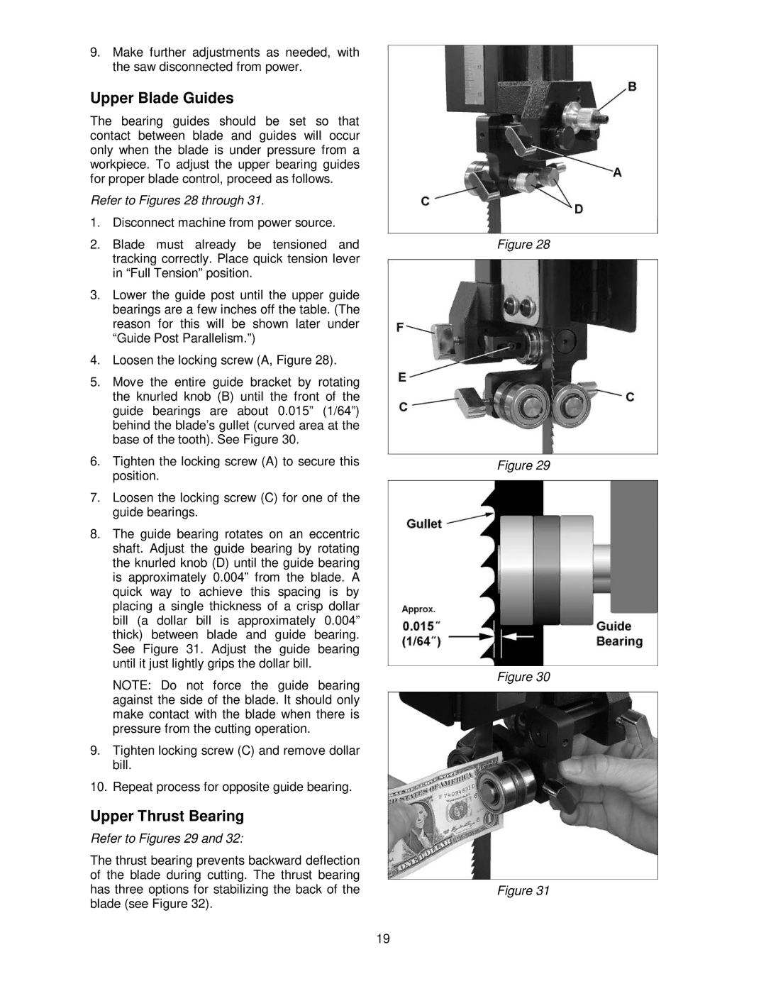
4.Loosen the locking screw (A, Figure 28).
5.Move the entire guide bracket by rotating the knurled knob (B) until the front of the guide bearings are about 0.015” (1/64”) behind the blade’s gullet (curved area at the base of the tooth). See Figure 30.
6.Tighten the locking screw (A) to secure this position.
7.Loosen the locking screw (C) for one of the guide bearings.
8.The guide bearing rotates on an eccentric shaft. Adjust the guide bearing by rotating the knurled knob (D) until the guide bearing is approximately 0.004” from the blade. A quick way to achieve this spacing is by placing a single thickness of a crisp dollar bill (a dollar bill is approximately 0.004” thick) between blade and guide bearing. See Figure 31. Adjust the guide bearing until it just lightly grips the dollar bill.
NOTE: Do not force the guide bearing against the side of the blade. It should only make contact with the blade when there is pressure from the cutting operation.
9.Tighten locking screw (C) and remove dollar bill.
10.Repeat process for opposite guide bearing.
Upper Thrust Bearing
Refer to Figures 29 and 32:
The thrust bearing prevents backward deflection of the blade during cutting. The thrust bearing has three options for stabilizing the back of the blade (see Figure 32).
Figure 28
Figure 29
Figure 30
Figure 31
19