Guide Post
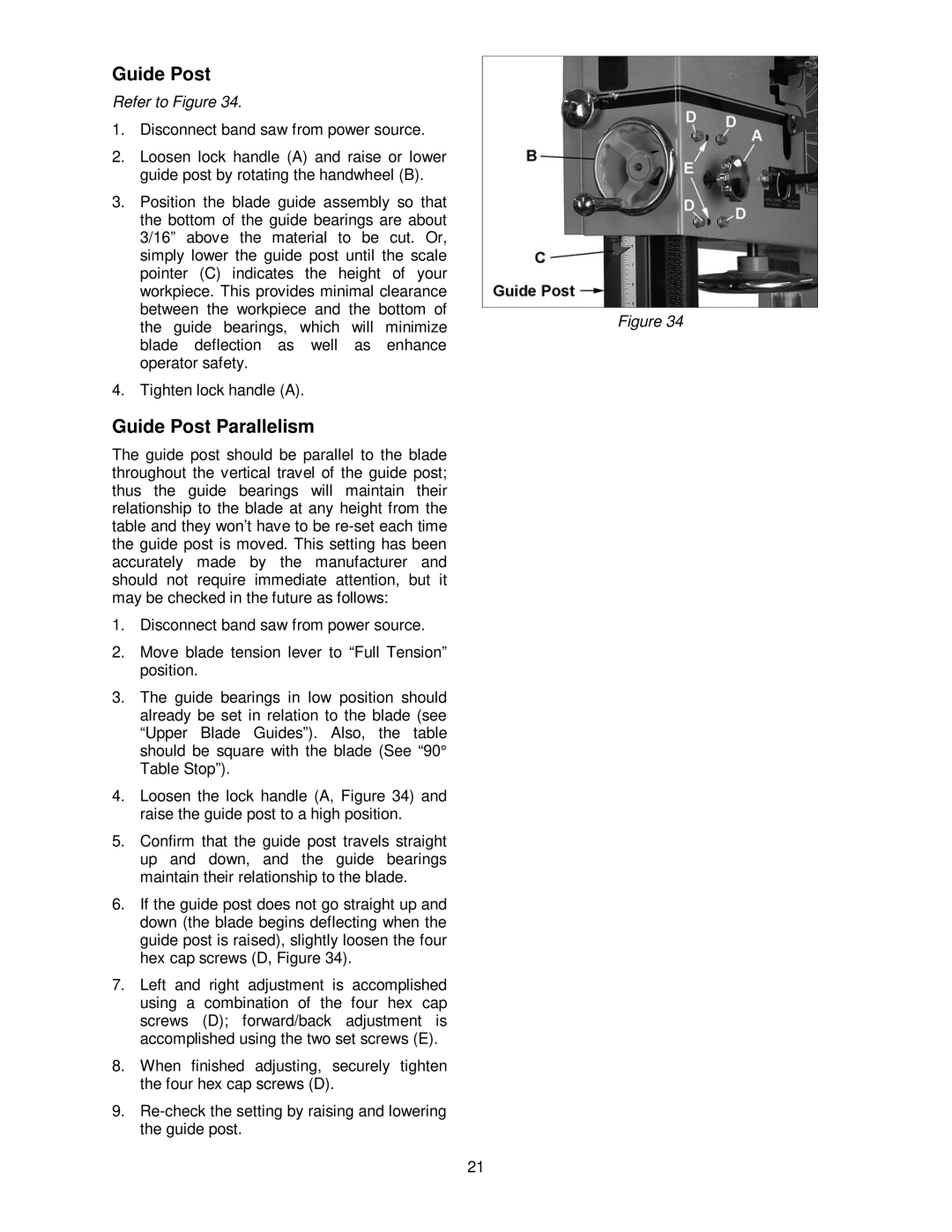
Refer to Figure 34.
1. | Disconnect band saw from power source. |
|
2. | Loosen lock handle (A) and raise or lower |
|
| guide post by rotating the handwheel (B). |
|
3. | Position the blade guide assembly so that |
|
| the bottom of the guide bearings are about |
|
| 3/16” above the material to be cut. Or, |
|
| simply lower the guide post until the scale |
|
| pointer (C) indicates the height of your |
|
| workpiece. This provides minimal clearance |
|
| between the workpiece and the bottom of | Figure 34 |
| the guide bearings, which will minimize | |
| blade deflection as well as enhance |
|
| operator safety. |
|
4. | Tighten lock handle (A). |
|
Guide Post Parallelism
The guide post should be parallel to the blade throughout the vertical travel of the guide post; thus the guide bearings will maintain their relationship to the blade at any height from the table and they won’t have to be
1.Disconnect band saw from power source.
2.Move blade tension lever to “Full Tension” position.
3.The guide bearings in low position should already be set in relation to the blade (see “Upper Blade Guides”). Also, the table should be square with the blade (See “90° Table Stop”).
4.Loosen the lock handle (A, Figure 34) and raise the guide post to a high position.
5.Confirm that the guide post travels straight up and down, and the guide bearings maintain their relationship to the blade.
6.If the guide post does not go straight up and down (the blade begins deflecting when the guide post is raised), slightly loosen the four hex cap screws (D, Figure 34).
7.Left and right adjustment is accomplished using a combination of the four hex cap screws (D); forward/back adjustment is accomplished using the two set screws (E).
8.When finished adjusting, securely tighten the four hex cap screws (D).
9.
21