SPINDLE TILTING
The machine should come to a complete stop before the spindle is tilted, and the insert with the oval slot should be placed into the table. Make sure the cutter does not touch the table or the fence when in tilted position.
1.Loosen the knob (C) on the front handwheel (D). See Figure 29.
2.Loosen the two locking handles (E) on both sides of the machine.
3.Turn the handwheel (D) to the required tilting angle shown on the indicator (F).
4.Tighten the knob (C) and locking handles (E).
FENCE ADJUSTMENT
1.To adjust the aluminum fence halves endwise, loosen the two fence locking levers
! | CAUTION: The aluminum fence halves |
|
should be adjusted inward so that the |
| |
| opening at the spindle is just enough to |
|
| clear the cutter. |
|
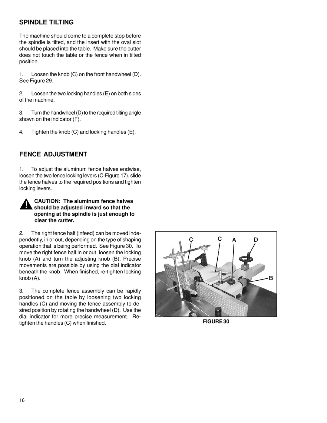
2. | The right fence half (infeed) can be moved inde- |
|
pendently, in or out, depending on the type of shaping |
| |
operation that is being performed. See Figure 30. To |
| |
move the right fence half in or out, loosen the locking |
| |
knob (A) and turn the adjusting knob (B). Precise |
| |
movements are possible by using the dial indicator |
| |
beneath the knob. When finished, |
| |
knob (A). |
| |
3. The complete fence assembly can be rapidly |
| |
positioned on the table by loosening two locking |
| |
handles (C) and moving the fence assembly to de- |
| |
sired position by rotating the handwheel (D). Use the |
| |
dial indicator for more precise measurement. Re- | FIGURE 30 | |
tighten the handles (C) when finished. | ||
16