ADJUSTMENTS
Control Panel Instructions
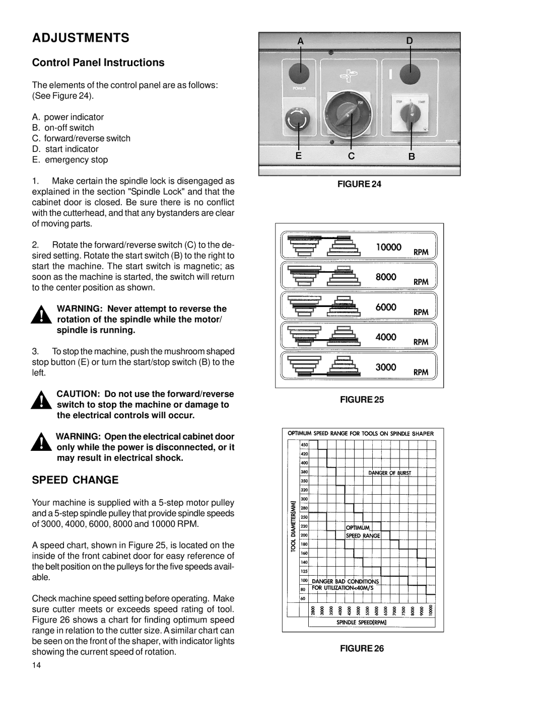
The elements of the control panel are as follows: (See Figure 24).
A.power indicator
B.
C.forward/reverse switch
D.start indicator
E.emergency stop
1.Make certain the spindle lock is disengaged as explained in the section "Spindle Lock" and that the cabinet door is closed. Be sure there is no conflict with the cutterhead, and that any bystanders are clear of moving parts.
2.Rotate the forward/reverse switch (C) to the de- sired setting. Rotate the start switch (B) to the right to start the machine. The start switch is magnetic; as soon as the machine is started, the switch will return to the center position as shown.
WARNING: Never attempt to reverse the ! rotation of the spindle while the motor/
spindle is running.
3. To stop the machine, push the mushroom shaped stop button (E) or turn the start/stop switch (B) to the left.
CAUTION: Do not use the forward/reverse ! switch to stop the machine or damage to
the electrical controls will occur.
WARNING: Open the electrical cabinet door ! only while the power is disconnected, or it
may result in electrical shock.
SPEED CHANGE
Your machine is supplied with a
A speed chart, shown in Figure 25, is located on the inside of the front cabinet door for easy reference of the belt position on the pulleys for the five speeds avail- able.
Check machine speed setting before operating. Make sure cutter meets or exceeds speed rating of tool. Figure 26 shows a chart for finding optimum speed range in relation to the cutter size. A similar chart can be seen on the front of the shaper, with indicator lights showing the current speed of rotation.
FIGURE 24
FIGURE 25
FIGURE 26
14
