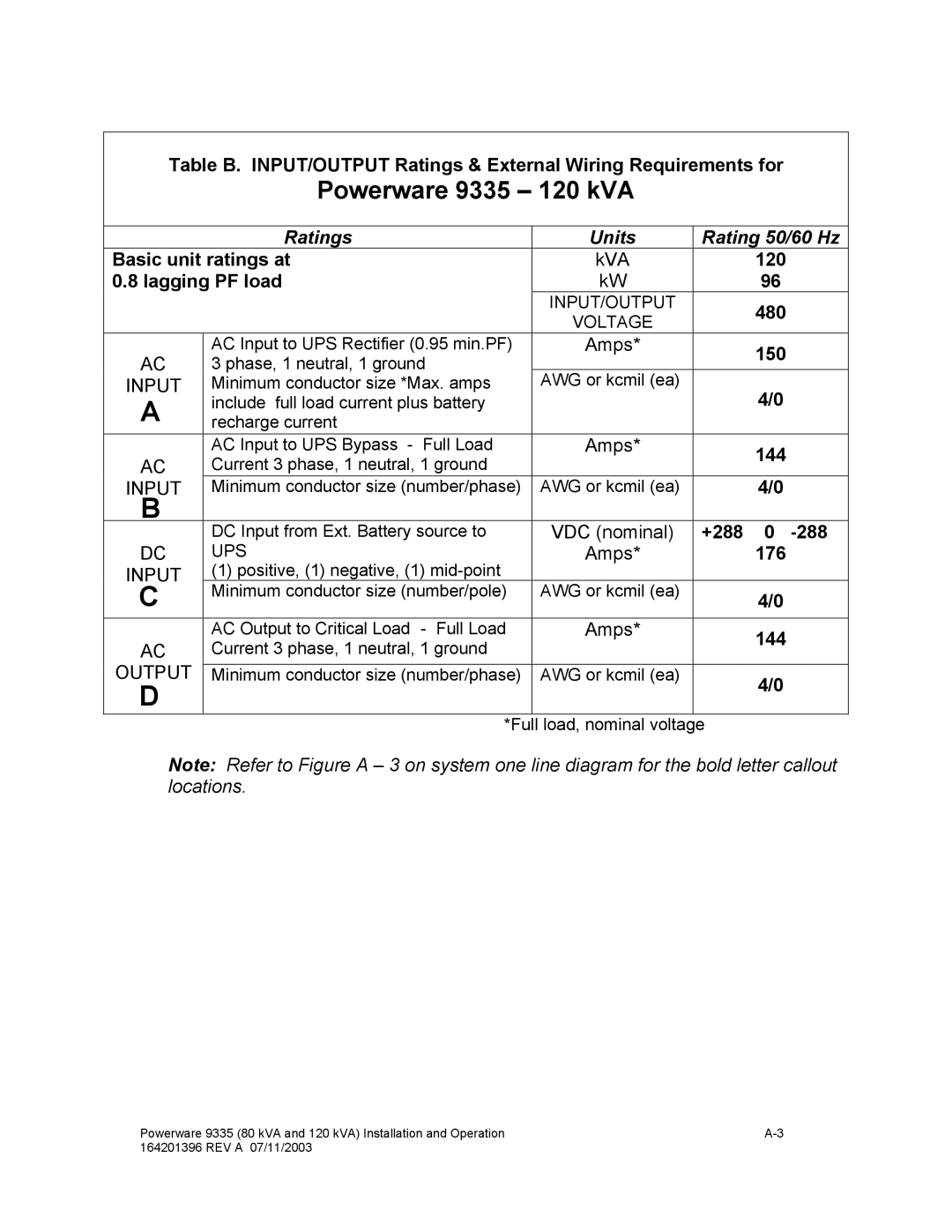
9335 specifications
The Powerware 9335 is a robust and efficient uninterruptible power supply (UPS) designed to deliver reliable power protection for critical applications. Expanding upon Eaton's tradition of offering advanced power management solutions, the Powerware 9335 is tailored for environments that demand high availability and uptime.One of the standout features of the Powerware 9335 is its double-conversion online topology, which ensures a continuous supply of clean and regulated power. This design operates without any transfer time to battery power, effectively protecting sensitive equipment from all types of power disturbances, including surges, sags, and outages.
The UPS is available in a range of power ratings, from 8 kVA to 40 kVA, making it versatile enough to support a variety of applications ranging from small server rooms to larger data centers. The modular architecture of the Powerware 9335 allows for seamless scalability, enabling users to add additional capacity or redundancy as their power needs evolve. This feature is particularly beneficial in dynamic environments where equipment and loads can frequently change.
Another significant characteristic of the Powerware 9335 is its high efficiency, often exceeding 94% in normal operation. This efficiency not only reduces energy costs but also minimizes heat generation, leading to lower cooling requirements. The UPS employs advanced technologies such as Intelligent Power Management and Smart APM (Adaptive Power Management) to optimize power usage, further enhancing its overall performance and reducing the total cost of ownership.
The user-friendly LCD display furnishes real-time data regarding UPS status, battery condition, and power settings, facilitating proactive management and monitoring. In addition, the unit can be monitored and managed remotely, ensuring that administrators can access critical information even when they are not on-site.
The Powerware 9335 also comes equipped with various connectivity options, including USB, serial, and SNMP for seamless integration into existing IT infrastructure. Additionally, advanced communication capabilities allow for integration with building management systems, ensuring comprehensive power management and reporting.
Safety is paramount, and the Powerware 9335 incorporates numerous features designed to protect both the UPS and connected equipment. This includes overload protection, battery health monitoring, and environmental monitoring, which collectively contribute to a resilient power protection strategy.
In summary, the Powerware 9335 is an exceptional UPS offering from Eaton, featuring high availability, scalability, efficiency, and robust management options. With its advanced technologies and features, it stands out as a premier choice for organizations seeking to safeguard their critical systems and data.

