1

2

3

4

5

6

7

8

9

10

H

G

+5VC 1 JD1 TXD232 2 RXD232 3

DTR 4

Customer_In 20 JD2

NW6009 Relay Control & Customer Interface

J4


TDX_Par

53

Serial Port

TXD-232

9

RXD-232

10

and XCP

Modem

11


+5V

7


PS+2418


PS+2419


+12VE62

Customer_In

12


Mains_OK

2

Common_Alarm

3


Ld_On_Inv

4

J4

NW4001 Control Electronics

J3


J1

12

NW6004 Bypass Control

H


Batt_Ch_Cntr


53


12


1


1


9


Thy_Batt_Neg


2


2


10


11


Thy_Batt_Pos

7


7


7


18


8


8


19


Tar_Bch_Neg_L 10


10


62


12


Tar_Bch_Neg_H 13


13


2

Battery charger

Tar_Bch_Pos_L 21


21


3

and battery

Tar_Bch_Pos_H 11


11


4

thyristor control

PS_Bch

15


15


G

signals


F

Mains_OK

1

2


3

13 Common_Alarm 1415

Ld_On_Inv

4

5


6

Batt_Low

7

8


9


10

Ld_On_Mains 11


12

+12VE +12VE +12VE +12VE +12VE

Batt_Low

5

Ld_On_Mains 6

Par_system_In

25

Par_system_Out

26

B_Ch_cntrl

27

K_Byp_Pos

28

K_Byp_Neg

29

T1_Par_L1

37

T2_Par_L1

39

T1_Par_L2

41

T2_Par_L2

43

T1_Par_L3

45

T2_Par_L3

47

Inv_Fail

60


Ld_Cntrl_Unit35 Reset_Cntrl55

5

U_Batt_Neg 4


4


6

U_Batt_Pos 5


5


25

I_Batt_Ch_Neg

9


9


I_Batt_Ch_Pos 30


30


26


27

Sel_Batt 14


14


28

U_Dc_Pos 34


34


29

U_Dc_Neg 40


40


37


39


41

Bst_On_Neg

26


26


43


F

45


27


27


47

I_Bst_Max_Neg 28


28


60


I_Bst_Max_Pos 29


29


35

I_Bst_Cntrl_K_

35


35


55

P


I_Bst_Cntrl_A_


A-13

E

D

C

B

A


23 +12VC

I_N

1

CN6


2


K_Inv_Status 1

CN23

CN34

K_Byp_Status 1

CN19

U_RCT_L1

3


U_RCT_L2

12


U_RCT_L3

14


Gen_On

1

X2


2

CN23

K1 1


Bypass_cntrl 1

CN22


K3

1

CN20


1

Off_Out13

31

32

30

24

56

57

58

33 K_soft_Start23


K_Batt

22


Thy_Batt_Pos 2928


Load_OFF

13


K_Batt_err

21


K_Inv

20


J7


Ld_Cntrl_Bus

1


2


Byp_Serv_Cntrl

3


4


Q2_Status

5


6


Byp_Serv_Cntrl

8


7


RXD_Par

10


9


M_S_Bus 1211


T1_Bus_Par_L1

1314

T2_Bus_Par_L1 1615

T1_Bus_Par_L2 1718

T2_Bus_Par_L2 2019

T1_Bus_Par_L3 2221

T2_Bus_Par_L3 2324

Connector_Error 2625

Inv_Fail_Bus 2728

Frq_Temp_Batt 3029

23

13

Booster

P 36

36


control

I_Bst_Cntrl_K_

38

38


31

signals

N


I_Bst_Cntrl_A_


32


N

39

39


30


Bst_On_Pos

31

31


32

32


24


Temp_Res 22

22

E

56


Temp_Boost 23

23

57


58


+12V_Driver 16


16


58


+12V_Driver 17

17


23-12V_Driver 20 20


28


29


13


D


21


20


J7 1


2


3


4


5


6


8


7


10


C


9


11


12


14


13


16


15


18


17


20


19


22


21


B


24


23


26


25


27


Drawn by :RMo

Date:

Signature :


28

Modification

Modification


29


Sheet : 1

of : 5


30


Checked by :

Date:

Signature :


Replace :

Date:

Signature :


Electrical Diagram


A


80 and 120 kVA S06-0001ULA


Powerware 9335

4

5

6

7

8

9

10

Page 91
Image 91
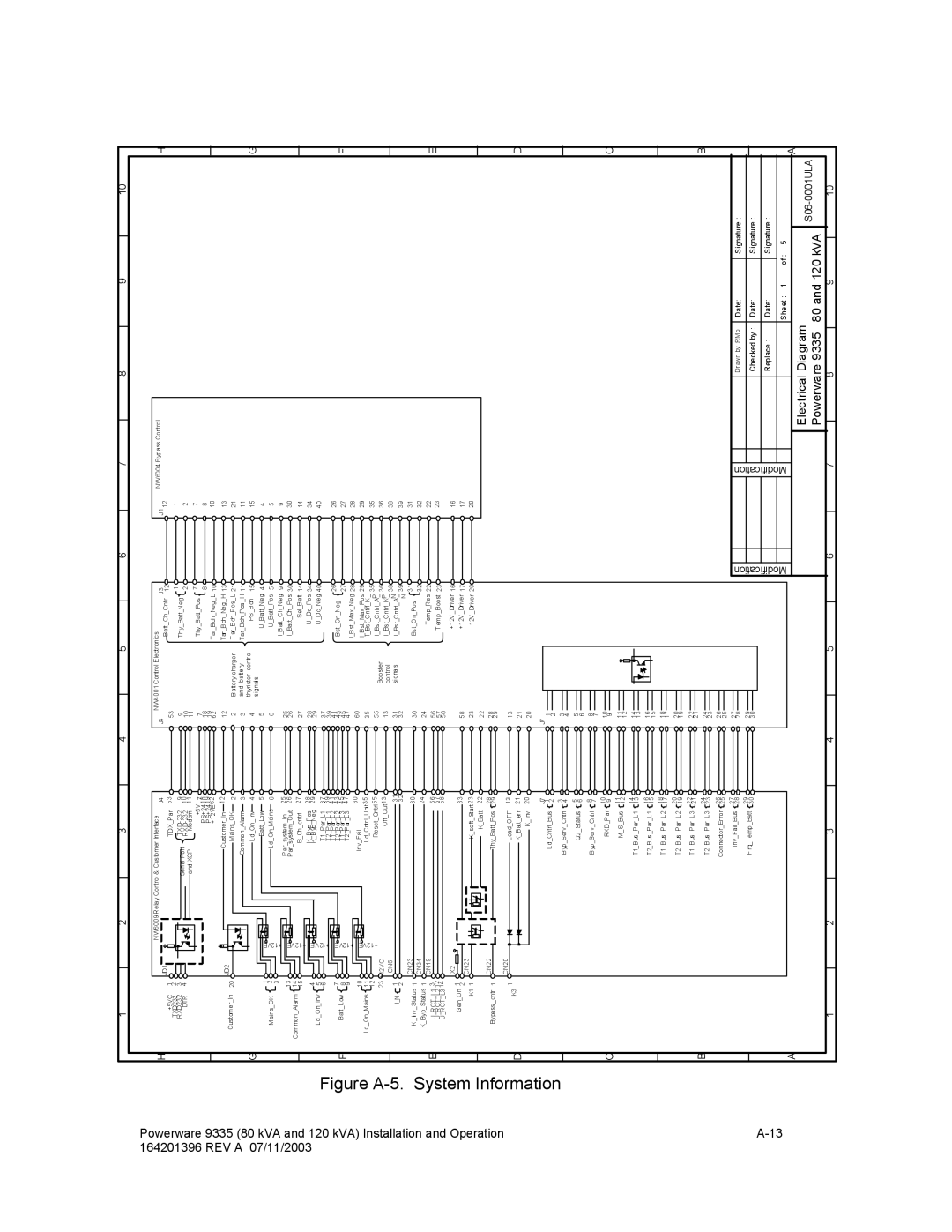
Powerware 9335 operation manual Electrical Diagram 120 kVA S06-0001ULA Powerware

9335 specifications

The Powerware 9335 is a robust and efficient uninterruptible power supply (UPS) designed to deliver reliable power protection for critical applications. Expanding upon Eaton's tradition of offering advanced power management solutions, the Powerware 9335 is tailored for environments that demand high availability and uptime.

One of the standout features of the Powerware 9335 is its double-conversion online topology, which ensures a continuous supply of clean and regulated power. This design operates without any transfer time to battery power, effectively protecting sensitive equipment from all types of power disturbances, including surges, sags, and outages.

The UPS is available in a range of power ratings, from 8 kVA to 40 kVA, making it versatile enough to support a variety of applications ranging from small server rooms to larger data centers. The modular architecture of the Powerware 9335 allows for seamless scalability, enabling users to add additional capacity or redundancy as their power needs evolve. This feature is particularly beneficial in dynamic environments where equipment and loads can frequently change.

Another significant characteristic of the Powerware 9335 is its high efficiency, often exceeding 94% in normal operation. This efficiency not only reduces energy costs but also minimizes heat generation, leading to lower cooling requirements. The UPS employs advanced technologies such as Intelligent Power Management and Smart APM (Adaptive Power Management) to optimize power usage, further enhancing its overall performance and reducing the total cost of ownership.

The user-friendly LCD display furnishes real-time data regarding UPS status, battery condition, and power settings, facilitating proactive management and monitoring. In addition, the unit can be monitored and managed remotely, ensuring that administrators can access critical information even when they are not on-site.

The Powerware 9335 also comes equipped with various connectivity options, including USB, serial, and SNMP for seamless integration into existing IT infrastructure. Additionally, advanced communication capabilities allow for integration with building management systems, ensuring comprehensive power management and reporting.

Safety is paramount, and the Powerware 9335 incorporates numerous features designed to protect both the UPS and connected equipment. This includes overload protection, battery health monitoring, and environmental monitoring, which collectively contribute to a resilient power protection strategy.

In summary, the Powerware 9335 is an exceptional UPS offering from Eaton, featuring high availability, scalability, efficiency, and robust management options. With its advanced technologies and features, it stands out as a premier choice for organizations seeking to safeguard their critical systems and data.